Spinal FrontiersPowered by NSpineWeekly alert sign-up
← Back
Spinal Frontiers · Patent Watch

New spine patents from the US and Europe

Powered byNSpine

Spine patents granted or published in the United States and Europe, newest first, each summarised in plain language with its drawing. Use the filters to see one device type, office or company, or search by company, inventor or number.

Where the patents come from

United States, August to September 2026

New this issue

16 granted patents and 1 published application from spine companies, issued up to 1 September 2026. The US patent databases we use had no later spine grants available when we checked on 28 October; they will be added in a coming weekly update.

We could not load this drawing for this issue.
See the drawings on the patent record →
US 12,721,613 B2
GrantedInstruments & access

Retractor with ratchet-locked sliding blade for lateral access

US 12,721,613 B2 · granted 1 September 2026

Owner
Spinal Elements, Inc. (USA)
Applicant
Spinal Elements, Inc.
Summary and claim

A surgical retractor in which an actuator slides one blade and a lock handle prevents it slipping back, used with a second blade assembly. The description refers to lateral transpsoas access to the spine.

Main claimPer the abstract (claims not read), covers a retractor with a sliding first blade driven by an actuator, a lock handle that blocks reverse movement, and a second blade assembly.

ContextLateral lumbar interbody fusion relies on stable retraction through the psoas.

Read the patent
We could not load this drawing for this issue.
See the drawings on the patent record →
US 12,721,732 B2
GrantedInterbody & cages

Expandable stand-alone cage with screw-blocking ring

US 12,721,732 B2 · granted 1 September 2026

Owner
Globus Medical, Inc. (USA)
Applicant
Globus Medical, Inc.
Summary and claim

An expandable interbody implant in which a screw-driven ramped carriage pushes the endplates apart while keeping an open graft channel between the vertebrae. Each endplate also accepts a bone screw, making it an integrated-fixation cage.

Main claimProtects an expandable implant whose endplates each carry a bone-fastener hole, with a frame-and-screw actuator for expansion plus an actuator plate and blocking ring that stop the fasteners backing out.

ContextStand-alone expandable cages combine height adjustment with integrated fixation to avoid supplemental plating.

Read the patent
We could not load this drawing for this issue.
See the drawings on the patent record →
US 12,714,411 B2
GrantedInstruments & access

Rack-and-pinion retractor with lockable, angulating blades

US 12,714,411 B2 · granted 25 August 2026

Owner
Atec Spine, Inc. (formerly Alphatec Spine) (USA)
Applicant
Alphatec Spine, Inc.
Inventors
David Considine, Andrew W. Rajek, Maximilian Garcia, Ethan Padgett, Alexis Fiechtner
Summary and claim

A table-mountable spinal retractor whose blades snap into shaped seats that stop them sliding, turning or tilting unintentionally. The description includes cervical exposures for disc removal or replacement.

Main claimProtects a retractor with a rack-and-pinion frame carrying two independently moving cabins, each arm holding a blade seat with an hourglass receptacle, latch, release and angulation knob.

ContextRetractor stability and blade control remain practical concerns in anterior cervical and other spinal exposures.

Read the patent
We could not load this drawing for this issue.
See the drawings on the patent record →
US 12,714,572 B2
GrantedInterbody & cages

Curved expandable interbody with pivoting inserter

US 12,714,572 B2 · granted 25 August 2026

Owner
Spinal Elements, Inc. (USA)
Applicant
Spinal Elements, Inc.
Summary and claim

A curved interbody implant whose upper and lower parts are spread apart by a screw mechanism once in the disc space. A deployment tool locks to the implant, can pivot relative to it and drives the expansion.

Main claimPer the abstract (claims not read), covers a curved implant expanded by a screw mechanism and a deployment tool that locks to, pivots on and actuates the implant.

ContextCurved expandable cages are designed to sit across the anterior disc space through a posterior or transforaminal approach.

Read the patent
We could not load this drawing for this issue.
See the drawings on the patent record →
US 12,714,573 B2
GrantedInterbody & cages

Expandable cage with swappable endplates

US 12,714,573 B2 · granted 25 August 2026

Owner
Life Spine, Inc. (USA)
Applicant
Life Spine, Inc.
Inventors
Daniel Predick
Summary and claim

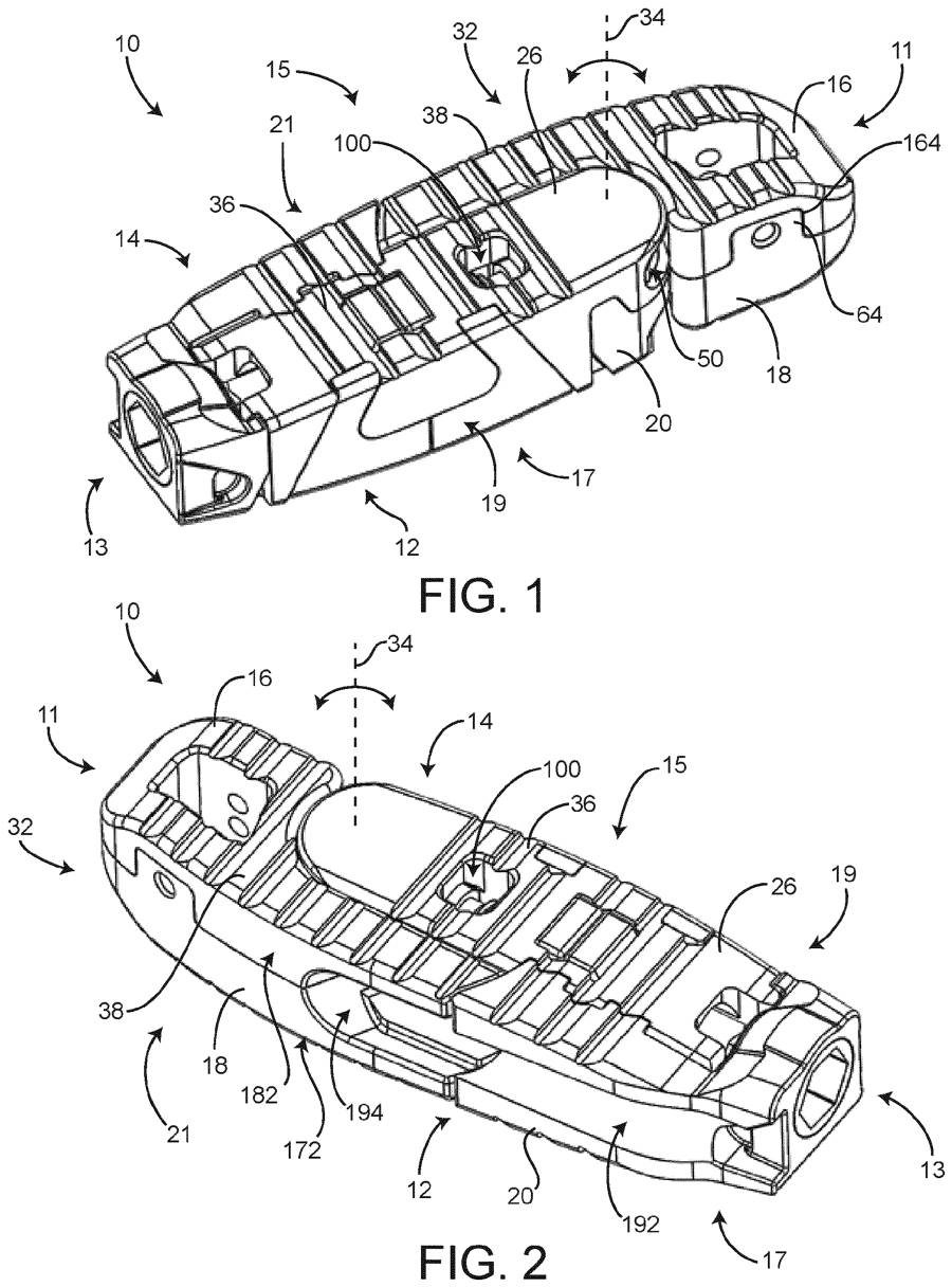
An expandable interbody implant whose upper and lower halves each consist of a base onto which different endplates can be attached, joined by a control assembly that drives expansion. Modular endplates allow footprint or angle to be chosen without changing the core mechanism.

Main claimProtects an expandable implant with upper and lower assemblies of a base plus selectively attachable endplates, with aligned graft windows in base and endplate, and a control assembly governing their relative movement.

ContextModularity is one way to reduce the inventory burden of expandable cage systems.

Read the patent
We could not load this drawing for this issue.
See the drawings on the patent record →
US 12,715,142 B2
GrantedNavigation & robotics

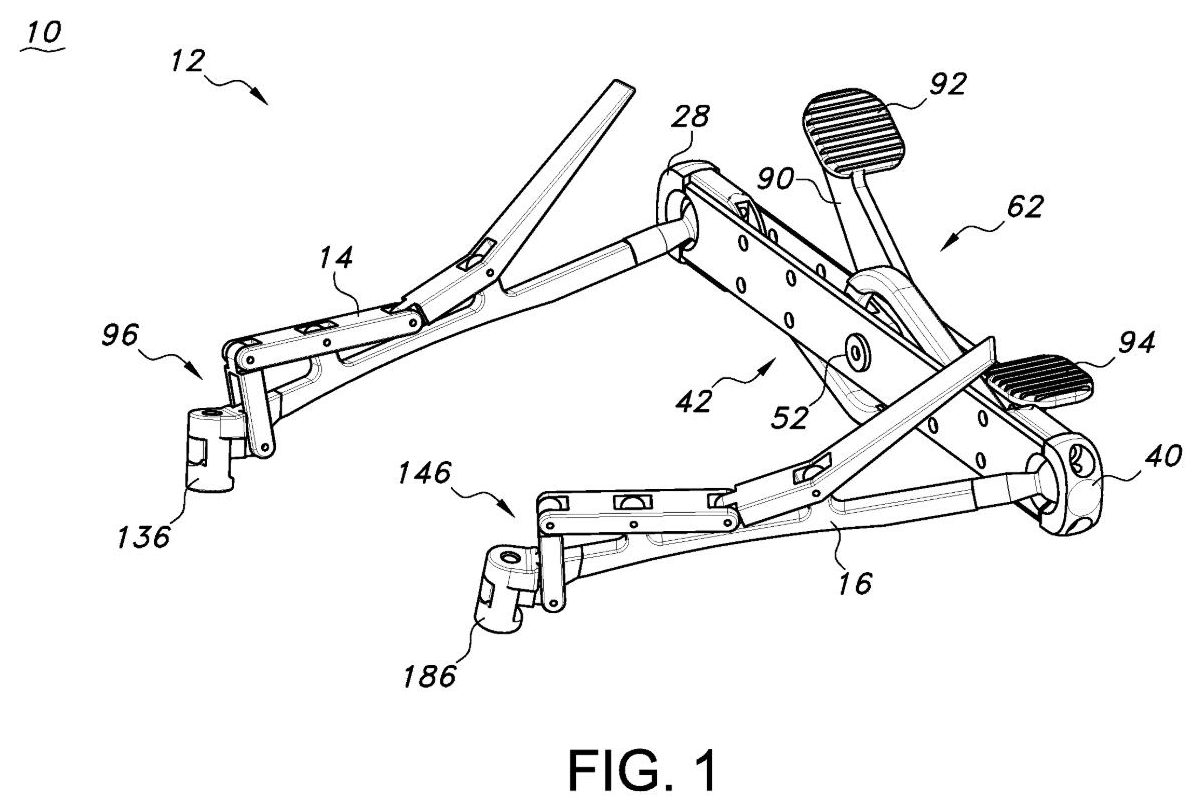
Two-arm robot that bends patient-specific spinal rods

US 12,715,142 B2 · granted 25 August 2026

Owner
Globus Medical, Inc. (USA)
Applicant
Globus Medical, Inc.
Inventors
Douglas Mandell, David C. Paul, Norbert Johnson, David Cleary, Danielle Reinhard
Summary and claim

An automated system in which one robot arm feeds and rotates a spinal rod while a second arm bends it between mandrels, the two moving in sync to produce a patient-specific contour. It is designed to work with a multi-arm surgical robot.

Main claimProtects a multi-arm surgical robot with a powered rod-holding end effector (feed and rotation rollers) on one arm and a powered mandrel bending end effector on the other, operating in synchronisation.

ContextAutomated, plan-based rod contouring is aimed at reproducing planned alignment more precisely than hand bending.

Read the patent
We could not load this drawing for this issue.
See the drawings on the patent record →
US 12,708,318 B2
GrantedOther

Faster neuromonitoring threshold search that avoids tetany

US 12,708,318 B2 · granted 18 August 2026

Owner
Atec Spine, Inc. (formerly Alphatec Spine) (USA)
Applicant
Alphatec Spine, Inc.
Inventors
Richard A. O'Brien, Gregg Johns, Robert Snow, James E. Gharib
Summary and claim

An intraoperative neuromonitoring method that ramps stimulation current to find the lowest level evoking a muscle response, then slows the pulse rate and confirms with a second pulse. It is intended for use during spinal procedures such as pedicle screw placement and lateral access.

Main claimProtects a stimulation system that, once a pulse evokes a response, delivers a confirming pulse at equal or lower frequency and equal or higher current and records the first current as the threshold if both respond.

ContextTriggered EMG thresholds are routinely used to check screw position and nerve proximity; this is surgical neuromonitoring, not neuromodulation.

Read the patent
We could not load this drawing for this issue.
See the drawings on the patent record →
US 12,708,343 B2
GrantedPlanning & software

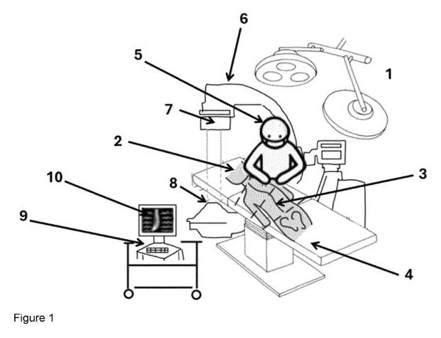
Calibrated long-length intraoperative X-ray views for alignment

US 12,708,343 B2 · granted 18 August 2026

Owner
Atec Spine, Inc. (formerly Alphatec Spine) (USA)
Applicant
Alphatec Spine, Inc.
Inventors
Shahram Amiri
Summary and claim

A system that tracks a mobile C-arm to stitch calibrated long single or stereo radiographs of the patient on the table, with measurement grids and parallax correction. Live images can be overlaid on pre-operative images or the surgical plan to check sagittal and coronal alignment during surgery.

Main claimPer the abstract (claims not read), covers tracking a mobile X-ray device to build calibrated long views on estimated anatomical planes and mapping new images onto those planes.

ContextIntraoperative assessment of global alignment is a recurring theme in deformity surgery, where standing films are unavailable on the table.

Read the patent
We could not load this drawing for this issue.
See the drawings on the patent record →
US 12,702,449 B2
GrantedPosterior fixation

Lengthenable growing rod for early-onset scoliosis

US 12,702,449 B2 · granted 11 August 2026

Owner
Globus Medical, Inc. (USA)
Applicant
Globus Medical, Inc.
Inventors
Joshua Charest, Michael Meccariello, Francis Torrente, Derrick Bingaman, Jeffrey David Gordon, Jeff Nichols
Summary and claim

An implantable growing rod with a housing, a fixed rod and an extendable rod driven out along the same axis by an internal gear drive, so the construct can be lengthened as a child grows. It is aimed at scoliosis in children and adolescents.

Main claimPer the abstract (claims not read), covers a growing rod assembly with a housing, a fixed rod, an expansion rod movable along the same axis and a driver assembly fixed to the housing that advances it.

ContextGrowth-friendly systems for early-onset scoliosis remain an active area following MAGEC supply and safety issues.

Read the patent
We could not load this drawing for this issue.
See the drawings on the patent record →
US 12,702,455 B2
GrantedInstruments & access

Navigated screw tower with built-in rod reducer

US 12,702,455 B2 · granted 11 August 2026

Owner
Globus Medical, Inc. (USA)
Applicant
Globus Medical, Inc.
Inventors
Matthew Bechtel, Caelan Allen, Neil R. Crawford, Thomas Calloway, Steven Chang, Norbert Johnson, Jeffrey Forsyth
Summary and claim

A screw extension tower that clips onto a pedicle screw tulip and carries a threaded driver to push the rod down into the screw head. The tower carries tracking markers so its position can be shown on the navigation display.

Main claimProtects a rod-reduction system combining a tulip-gripping screw tower, a threaded driver and housing for reduction, and a camera-based tracking system that displays the tower relative to the patient's images.

ContextCombining reduction instruments with navigation fits the wider move to navigated and robotic posterior fixation.

Read the patent
We could not load this drawing for this issue.
See the drawings on the patent record →
US 12,702,504 B2
GrantedNavigation & robotics

Robot control with on-screen tool-path collision warning

US 12,702,504 B2 · granted 11 August 2026

Owner
Globus Medical, Inc. (USA)
Applicant
Globus Medical, Inc.
Inventors
Peter L. Bono, James D. Lark, John S. Scales, Thomas J. Lord
Summary and claim

Software for a multi-axis surgical robot that lets the surgeon draw a tool path over images of the spine, for tasks such as bone and disc removal and hardware insertion. The system checks the path against the selected tool's dimensions.

Main claimProtects a robotic system in which the user selects a tool and draws a proposed path on the displayed image, and the computer warns if that path would make the tool interfere with the surgical site.

ContextSpine robots are moving from screw trajectory guidance towards robot-executed decompression and disc preparation.

Read the patent
We could not load this drawing for this issue.
See the drawings on the patent record →
US 12,702,565 B2
GrantedInterbody & cages

Anterior expandable cage with adjustable height and lordosis

US 12,702,565 B2 · granted 11 August 2026

Owner
Globus Medical, Inc. (USA)
Applicant
Globus Medical, Inc.
Inventors
Colm McLaughlin, Jason Zappacosta
Summary and claim

An expandable anterior interbody spacer with ramped endplates and separate anterior and posterior actuators, which can be driven together or individually to set height and lordotic angle. It is described for the lumbosacral spine.

Main claimClaims a method of placing an implant with ramped endplates, sliding-pivoting actuators and a screw drive between adjacent bones and rotating the actuator to spread the endplates.

ContextExpandable ALIF devices aim to restore segmental lordosis through a smaller insertion profile.

Read the patent
We could not load this drawing for this issue.
See the drawings on the patent record →
US 2026/0224298 A1
ApplicationNavigation & robotics

Navigation display that shows trajectory alignment as disc and cylinder

US 2026/0224298 A1 · published 6 August 2026

Owner
Atec Spine, Inc. (formerly Alphatec Spine) (USA)
Applicant
Alphatec Spine, Inc.
Inventors
John B. Clayton, Kevin J. Frank, Kevin T. Foley, David A. Vaughn, Jeff Justis
Summary and claim

An optical navigation method with a camera fixed relative to the surgical site and the operated body part restrained on the table, tracking instruments fitted with marker arrays. The description uses pedicle screw placement in the lumbar and thoracic spine as examples.

Main claim (pending, not yet granted)Claims a method showing instrument alignment in which the planned trajectory is drawn as a flat disc and the tracked guide as a 3D cylinder, alignment being reached when the cylinder sits within the disc's central circle.

ContextPending application; a published application does not mean a patent will be granted in this form.

Read the application
We could not load this drawing for this issue.
See the drawings on the patent record →
US 12,697,145 B2
GrantedPosterior fixation

Low-profile small pedicle screw linked by side plates

US 12,697,145 B2 · granted 4 August 2026

Owner
Globus Medical, Inc. (USA)
Applicant
Globus Medical, Inc.
Inventors
David Leff
Summary and claim

A compact pedicle screw whose two-part head is joined sideways to a plate-like connector rather than a conventional rod, aimed at a near-zero-profile construct. A locking mechanism clamps the head halves together so the screw can no longer swivel or slide along the connector.

Main claimProtects a pedicle screw with an upper and lower head body, a transverse connector made of two parallel plates either side of the head, and a lock that fixes the bodies together via prongs engaging grooves in the plates.

ContextLow-profile posterior fixation is of particular interest in thin patients and in the paediatric and cervicothoracic spine.

Read the patent
We could not load this drawing for this issue.
See the drawings on the patent record →
US 12,697,150 B2
GrantedSI joint

SI joint fusion screw with free-spinning outer sleeve

US 12,697,150 B2 · granted 4 August 2026

Owner
Life Spine, Inc. (USA)
Applicant
Life Spine, Inc.
Inventors
David T. Mehl, Ali H. Mesiwala
Summary and claim

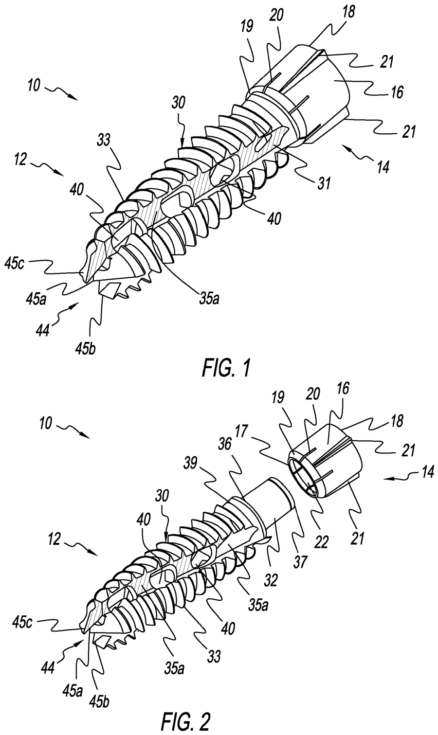
A sacroiliac fusion implant made of a threaded screw with cutting flutes that collect bone shavings, carried inside a sleeve that turns freely on the screw. The flutes are intended to retain harvested bone at the joint.

Main claimProtects an SI joint fusion implant comprising a fluted, threaded screw and a sleeve coupled by matching engagement geometries that keep them axially joined while letting the sleeve rotate freely.

ContextSI joint fusion is a growing market with screw-type, triangular and allograft implants competing.

Read the patent
We could not load this drawing for this issue.
See the drawings on the patent record →
US 12,697,228 B2
GrantedInterbody & cages

Lateral cage with independent front and back height adjustment

US 12,697,228 B2 · granted 4 August 2026

Owner
Globus Medical, Inc. (USA)
Applicant
Globus Medical, Inc.
Summary and claim

An expandable lateral interbody device whose anterior and posterior edges can be raised or lowered separately, allowing both height and lordosis to be set in situ. Openings in the trailing end give tool access to the actuators and allow graft to be added after expansion.

Main claimProtects a lateral expandable fusion device with two endplates, sliding anterior and posterior translation bars, pivoting joists and a separate actuator for each side that tilts the endplate front or back.

ContextAdjustable-lordosis expandable cages are among the most heavily patented spine device categories.

Read the patent
We could not load this drawing for this issue.
See the drawings on the patent record →
US 12,697,229 B2
GrantedCervical

Anterior cervical plate that locks onto the interbody spacer

US 12,697,229 B2 · granted 4 August 2026

Owner
Globus Medical, Inc. (USA)
Applicant
Globus Medical, Inc.
Inventors
Kurt Faulhaber, Bala Sundararajan
Summary and claim

A plating system for anterior fusion in which small retainer plates sit on a base plate and are screwed into the disc spacer, tying plate and cage together. The description focuses on cervical fusion.

Main claimClaims a method of inserting a spacer into the disc space, placing a base plate with a bridge over it, driving fasteners through a retainer plate into the spacer so it pivots on the bridge, then fixing the base plate to the vertebral bodies.

ContextIntegrating the plate with the cage is one route to lower-profile anterior cervical constructs.

Read the patent

United States, July 2026

Earlier in 2026

11 granted patents and 2 published applications from the main spine companies.

Implants

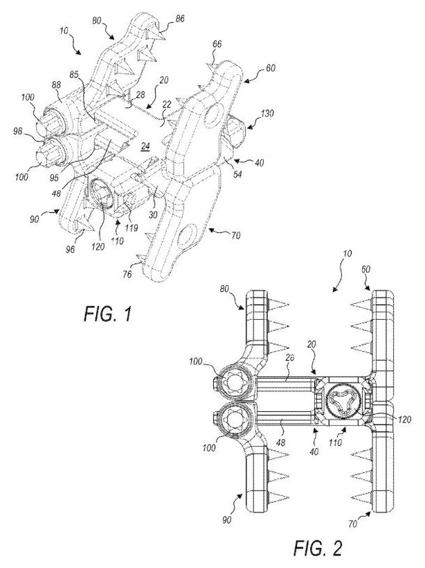
FIGS. 1–2, US 12,685,646 B2. Drawing via Espacenet.
GrantedPosterior fixation

Expandable interspinous process fixation device

US 12,685,646 B2 · granted 21 July 2026

Owner
Globus Medical
Assignee
Globus Medical, Inc.
Inventors
Matthew Bechtel, Hilliary Kopp
Summary and claim

A central ramp pushes two endplates apart once the device sits between the spinous processes. Each plate carries fixed or adjustable spikes that bite into the processes, to stabilise the segment and support fusion.

Main claimA central ramp and a driving ramp sit between the two endplates; moving them towards each other spreads the endplates apart, while retaining elements hold the sliding spinous-process plates.

ContextSpinous process plates are an established option for supplemental posterior fixation. The new element here is expansion in situ, so the device can go in collapsed.

Read the patent
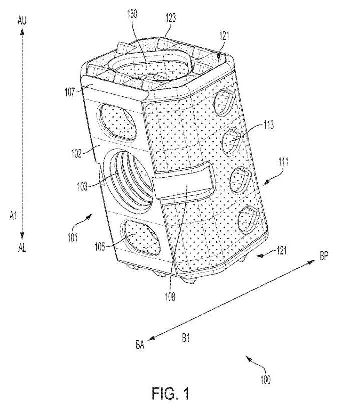
FIG. 1, US 12,690,972 B2. Drawing via Espacenet.
GrantedInterbody

Expandable interbody device with curved-pin fixation

US 12,690,972 B2 · granted 28 July 2026

Owner
Medtronic
Assignee
Warsaw Orthopedic, Inc.
Inventors
Loic Josse, Muriel Cazin
Summary and claim

An interbody cage anchored by curved bone pins. A hollow guide tool drives the pins through seats in a connector plate, where they pivot into the vertebral bodies.

Main claimCurved bone pins turn within seats in a connector plate so that their tips splay outwards, away from the plate’s axis, into the bone.

ContextMost stand-alone cages anchor with screws or blades. Curved pins placed through one front-facing tool are a less common route. The title and abstract emphasise different things, so the claims decide what is protected.

Read the patent
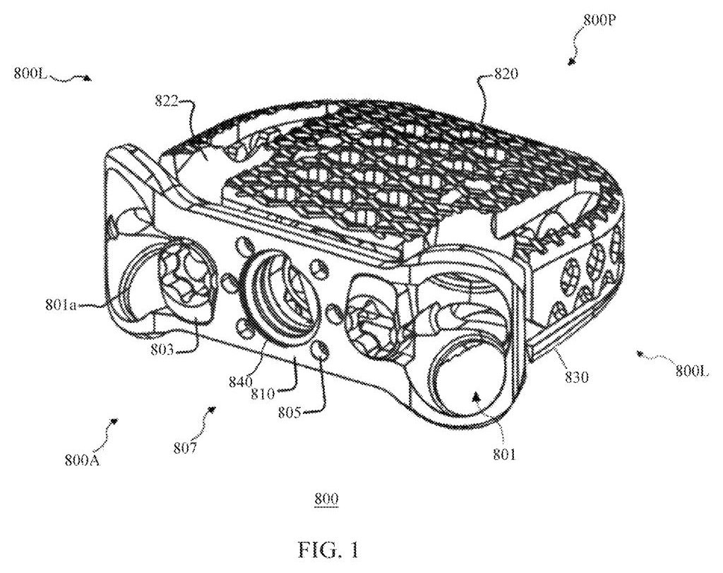
FIG. 1, US 12,678,291 B2. Drawing via Espacenet.
GrantedCorpectomy

3D-printed cervical corpectomy cage

US 12,678,291 B2 · granted 14 July 2026

Owner
Medtronic
Assignee
Warsaw Orthopedic, Inc.
Inventors
Keith E. Miller, Julien J. Prevost
Summary and claim

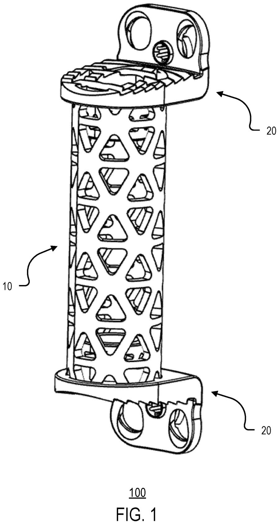
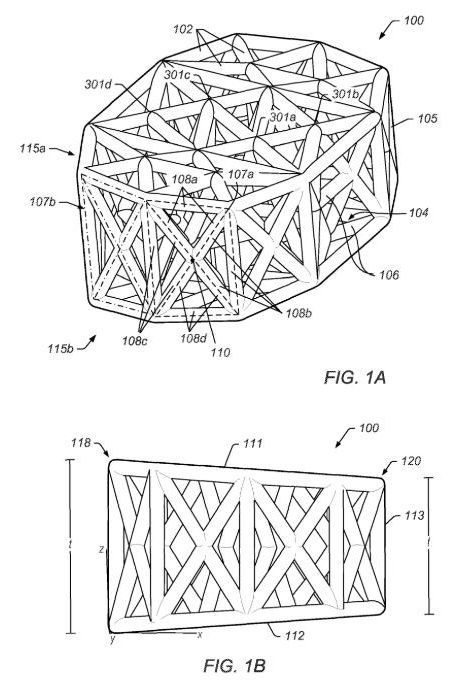
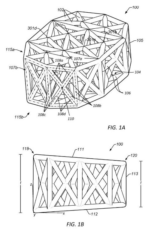
A printed metal vertebral body replacement for the cervical spine. A random (stochastic) lattice fills the body to lower stiffness and improve radiolucency, and porous lattice endplates are meant for bone ingrowth.

Main claimA cervical corpectomy cage built from six separate lattice regions (front, back, both sides and both endplates) around a hollow vertical channel, with anti-migration features on both endplates.

ContextPrinted titanium corpectomy cages are already sold by several companies. The stated aims here are lower stiffness and better post-operative imaging.

Read the patent
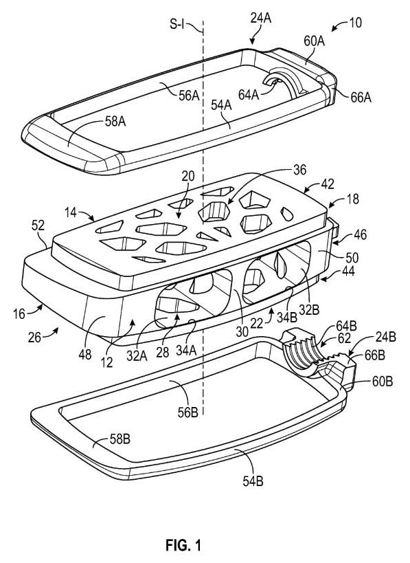
FIG. 1, US 12,678,296 B2. Drawing via Espacenet.
GrantedInterbody

Intervertebral implant with porous core

US 12,678,296 B2 · granted 14 July 2026

Owner
Highridge Medical (formerly Zimmer Biomet Spine)
Assignee
Highridge Medical, LLC
Inventors
Samuel Jebsen, Ryan Watson, Marc Bereau, Edouard Jouan
Summary and claim

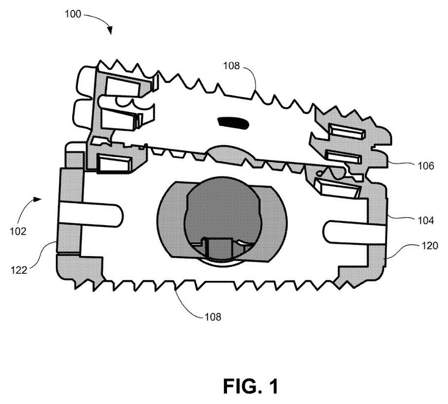
A cage frame surrounds a porous core whose upper and lower faces lie open to the vertebral endplates. The drawing also shows separate endplate frames that clip to the cage.

Main claimA single-piece porous structure with an internal cavity connected to pores on both endplate-facing surfaces, so graft material spreads through the pores while the structure stays compressible.

ContextSolid frames around porous cores are a crowded design space. Interest lies in how the frame and porous structure are joined.

Read the patent
FIGS. 1–3, US 12,690,894 B2. Drawing via Espacenet.
GrantedPedicle screwDeformity

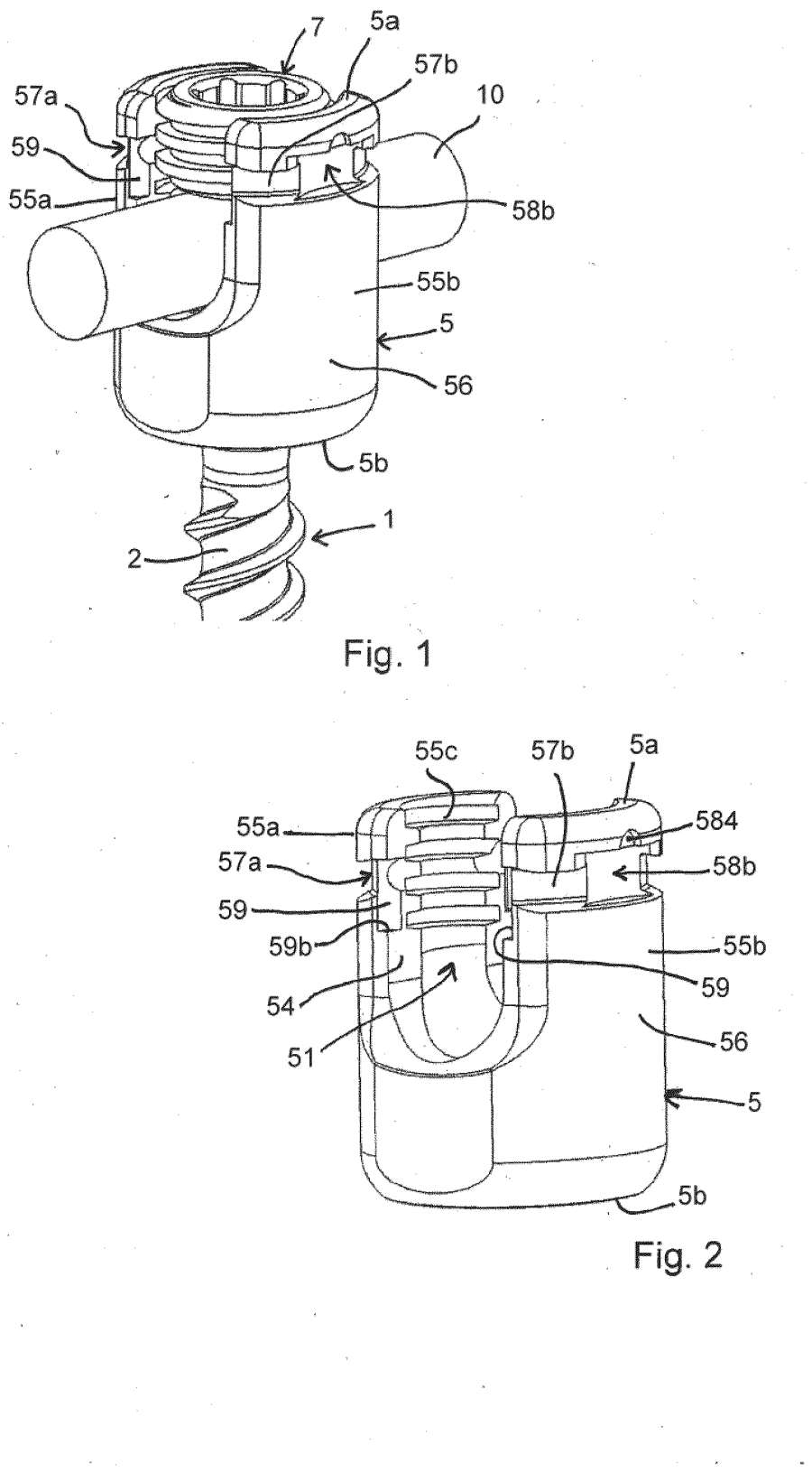
Polyaxial screw for deformity correction

US 12,690,894 B2 · granted 28 July 2026

Owner
Globus Medical (NuVasive merged in 2023)
Assignee
NuVasive, Inc.
Inventors
Niall Casey, Robert German, Scott Lish
Summary and claim

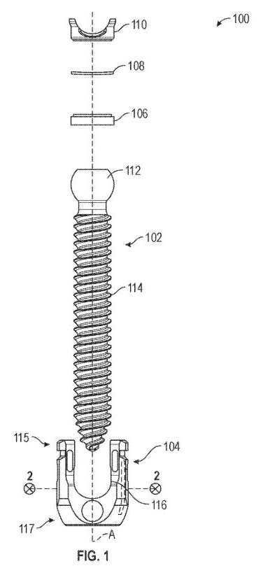
Filed under the title “Systems and methods for correcting spinal deformities”, but the first claim covers a polyaxial screw. A collar inside the tulip, with two opposed convex outer faces, couples the screw head to the receiver.

Main claimThe collar between screw head and receiver has two opposed convex faces joined by two flat facets, giving a non-round collar that seats against a rounded feature of the receiver.

ContextPolyaxial pedicle screws are a mature field, so any novelty sits in the collar geometry. The broad title says little about what the claims protect.

Read the patent
FIG. 1, US 12,678,201 B2. Drawing via Espacenet.
GrantedPedicle screw

Bone anchor with limited angulation

US 12,678,201 B2 · granted 14 July 2026

Owner
Highridge Medical (formerly Zimmer Biomet Spine)
Assignee
Highridge Medical, LLC
Inventors
Allison Christine Capote
Summary and claim

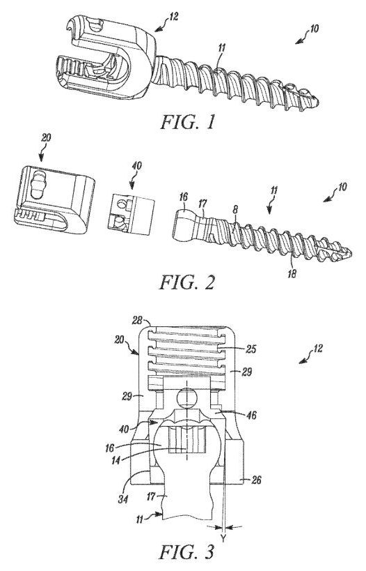
A screw-and-housing assembly in which a second bore in the lower part of the housing engages the screw to limit how far it can angle.

Main claimThe housing’s second bore is a rounded square, with a chamfer and curved bevels around it; this shape is what governs how far the screw can angle.

ContextScrews that restrict angulation sit between monoaxial and fully polyaxial designs. This is one more mechanical way of setting that limit.

Read the patent
FIG. 1, US 12,678,202 B2. Drawing via Espacenet.
GrantedSublaminar bandDeformity

Flexible fastening system

US 12,678,202 B2 · granted 14 July 2026

Owner
Stryker
Assignee
K2M, Inc.
Inventors
Behrooz Akbarnia, Burt Yaszay, Brandon Moore, Stuart Weikel, Clint Boyd
Summary and claim

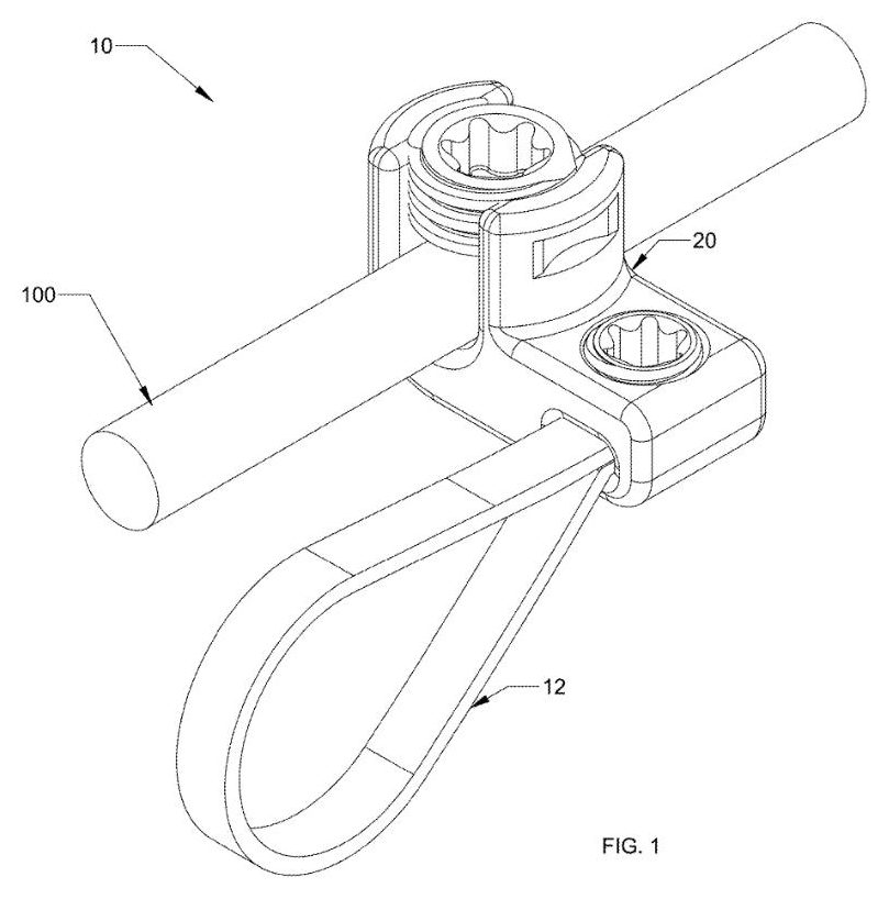
A flexible band loops around a bony element such as the lamina, passes through a housing that clamps onto the rod, and is locked with a set screw.

Main claimA method: loop and tension the band around the bone, then lock both the rod and the band in the housing with one set screw, through passages that run parallel.

ContextSublaminar band systems are established in deformity surgery, often as an alternative to hooks or screws at difficult levels.

Read the patent

Instruments

FIG. 1, US 12,690,900 B2 (sheet rotated to read upright). Drawing via Espacenet.
GrantedReduction

Linked instrument for moving vertebrae

US 12,690,900 B2 · granted 28 July 2026

Owner
Medtronic
Assignee
Warsaw Orthopedic, Inc.
Inventors
Roy K. Lim, Mark C. Dace, Richard Q. Brown, Adam D. Glaser
Summary and claim

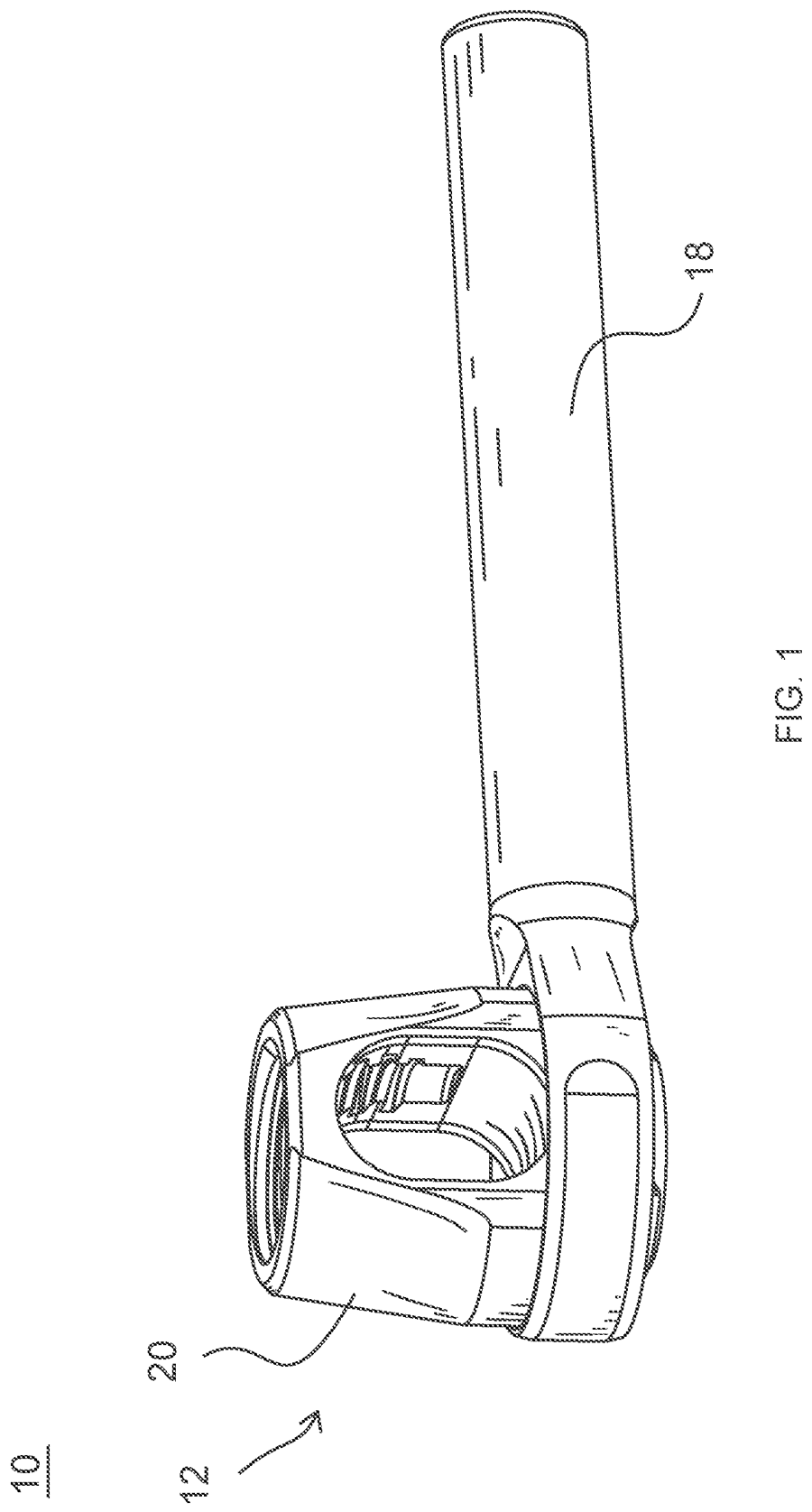
Two arms each lock onto a bone screw in a different vertebra through a ball-type joint. A linkage engages both joints at once, so the two vertebrae can be moved relative to each other.

Main claimA ball-and-socket link between two screw-mounted arms, in which the socket slides within a frame from a free position to a locked one, fixing the two vertebrae relative to each other.

ContextMulti-level manipulation tools are common, especially for derotation in scoliosis. What this patent specifies is the ball-joint linkage between levels.

Read the patent
FIG. 1, US 12,678,300 B2. Drawing via Espacenet.
GrantedSmart implant

Telemetry trial for digital implant

US 12,678,300 B2 · granted 14 July 2026

Owner
Medtronic
Assignee
Warsaw Orthopedic, Inc.
Inventors
Kevin T. Foley, Steven D. Glassman, Adam D. Glaser, Newton H. Metcalf Jr., Jerald L. Redmond
Summary and claim

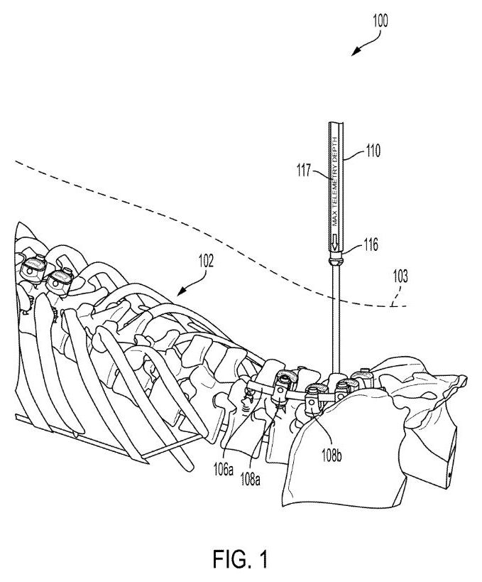
A trial instrument for sizing an implant that carries sensors: handle, shaft, a rotating head and an indicator showing its orientation. The drawing marks a maximum telemetry depth on the shaft.

Main claimThe trial carries a transmitter that sends a test signal, plus a gauge showing the threshold distance, so wireless read-out can be checked before the real implant goes in.

ContextInstruments for placing sensor-equipped implants are new territory. The depth marking suggests the trial also checks that the implant will sit close enough for wireless read-out.

Read the patent

Robotics and navigation

FIG. 1, US 2022/0241017 A1, the earlier published application of this patent. The granted patent’s drawings are not yet online. Drawing via Espacenet.
GrantedRoboticsPlanning

Rod insertion planning and rod insertion

US 12,685,591 B2 · granted 21 July 2026

Owner
Medtronic
Assignee
Mazor Robotics Ltd.
Inventors
Dany Junio
Summary and claim

Software takes the surgical images and the planned screw-tower positions, identifies soft tissue and bone, and calculates an entry point and path for passing the rod.

Main claimPlan the rod’s entry point and path from the images and tower positions, then monitor the robotic arm and recalculate the path whenever its actual position drifts beyond a set threshold.

ContextRobotic platforms already plan screw trajectories. Planning the rod pass itself, including the soft-tissue route, extends that to the next step.

Read the patent
FIG. 1, US 12,694,558 B2 (sheet rotated to read upright). Drawing via Espacenet.
GrantedNavigationImaging

Identifying features in intra-operative images

US 12,694,558 B2 · granted 28 July 2026

Owner
Medtronic, with Johns Hopkins University
Assignee
Medtronic Navigation, Inc. and The Johns Hopkins University
Inventors
Patrick A. Helm, Jeffrey H. Siewerdsen, Ali Uneri, Craig K. Jones, Yixuan Huang, Xiaoxuan Zhang
Summary and claim

The imaging system acquires overlapping views from several perspectives. The software then identifies anatomical features automatically and uses them for registration.

Main claimCombine candidate regions from several image views to locate a feature automatically, then label its position in two separate output views.

ContextAutomatic registration from intra-operative imaging is where navigation is heading. The co-assignment with Johns Hopkins points to an academic origin for the method.

Read the patent

Sensing and smart implants

FIG. 1, US 2026/0215732 A1. Drawing via Espacenet.
ApplicationSmart implantAdjacent level

Smart spine implant for adjacent-level assessment

US 2026/0215732 A1 · published 30 July 2026

Owner
Medtronic
Assignee
Warsaw Orthopedic, Inc.
Inventors
Arjun Siby Kurian, Newton H. Metcalf Jr., Kevin T. Foley
Summary and claim

Sensors built into the screw-rod construct take measurements after surgery. The system uses them to assess the construct and the levels next to it, and to predict problems such as adjacent-segment disease.

Main claim (pending, not yet granted)Combine sensor readings from the fused construct with readings from an implant at a different level to determine the patient’s condition.

ContextSensor-equipped spinal implants remain largely experimental.

Read the application
FIG. 1, US 2026/0198890 A1 (sheet rotated to read upright). Drawing via Espacenet.
ApplicationBone qualitySensing

Detecting sound in a bone

US 2026/0198890 A1 · published 16 July 2026

Owner
Johnson & Johnson
Assignee
DePuy Synthes Products, Inc.
Inventors
Jeffrey Bizub
Summary and claim

An emitter sends sound waves into one end of a bone and a receiver picks them up at the other. A circuit compares the two signals to give an indication of bone quality. The first drawing shows an interbody implant.

Main claim (pending, not yet granted)An emitter at one end of a bone, a receiver at the other, and a circuit that compares the sent and received sound waves to indicate bone quality.

ContextUltrasound measurement of bone quality exists for screening at peripheral sites. Measuring it at the spine during surgery would be new.

Read the application

Europe, October to November 2026

New this issue

17 European grants and 12 applications from spine applicants, published by the EPO in October 2026.

We could not load this drawing for this issue.
See the drawings on the patent record →
EP 4502944 B1
GrantedPlanning & software

Updating a screw plan intraoperatively without external registrationNew · week 1

EP 4502944 B1 · granted (B1 published) 4 November 2026

Owner
Mazor Robotics Ltd. (Israel; Medtronic)
Applicant
Mazor Robotics Ltd.
Inventors
Ido Zucker
Summary and claim

Software that finds the vertebrae in intraoperative images and maps a preoperative implant plan onto them by treating planned screws as linked pairs of vectors. This lets the plan follow any shift in the anatomy without a separate registration step.

Main claimProtects a system that stores a preoperative plan of hardware positions, identifies the anatomical features in intraoperative images, converts planned hardware into vectors and superimposes fixed pairs of them on those features so the plan is updated for anatomical shift.

ContextRobotic spine platforms are competing to cut registration time and intraoperative radiation.

Read the patent
We could not load this drawing for this issue.
See the drawings on the patent record →
EP 3443888 B1
GrantedNavigation & robotics

Navigation display that shows or hides individual segmented spinal partsNew · week 1

EP 3443888 B1 · granted (B1 published) 28 October 2026

Owner
Augmedics Inc. (USA)
Applicant
Augmedics Inc.
Inventors
Krzysztof B. Siemionow, Cristian J. Luciano, Edwing Isaac Mejia Orozco
Summary and claim

A spinal navigation system that builds a 3D model of the patient's spine split automatically into separate parts, and lets the surgeon choose which parts appear on a head-tracked 3D display. The aim is to declutter the view during planning and live navigation.

Main claimProtects a navigation system with segmented 3D spinal anatomy data, an image generator, tracking of the surgeon's head, the display and the patient, and a 3D display in which selected spinal sections can be shown while others are hidden.

ContextAugmented-reality headsets and automatic segmentation are converging in spine navigation.

Read the patent
We could not load this drawing for this issue.
See the drawings on the patent record →
EP 4437983 B1
GrantedPosterior fixation

Tulip that makes the same screw head uniplanar or polyaxialNew · week 1

EP 4437983 B1 · granted (B1 published) 28 October 2026

Owner
Biedermann Technologies GmbH & Co. KG (Germany)
Applicant
Biedermann Technologies GmbH & Co. KG
Inventors
Lutz Biedermann, Timo Biedermann, Berthold Dannecker
Summary and claim

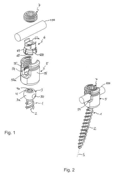
A modular rod-receiving head that accepts two kinds of screw shank: one is restricted to swivelling in a single plane, the other can angle freely. Matching recesses in the pressure member and receiving part provide the restriction, so one tulip design serves both uses in spinal surgery.

Main claimProtects a coupling device with a receiving part and pressure member that clamps an inserted screw head, characterised by aligned recesses in the pressure member and receiving part that engage a feature on one anchor type so it pivots in only one plane, while another anchor type pivots in several planes.

ContextUniplanar screws are widely used in deformity correction; modular systems reduce implant inventory.

Read the patent
We could not load this drawing for this issue.
See the drawings on the patent record →
EP 4827632 A1
ApplicationInstruments & access

Skin marking guide for two-portal endoscopic spine surgeryNew · week 1

EP 4827632 A1 · published 28 October 2026

Owner
Amplify Surgical, Inc. (USA)
Applicant
Amplify Surgical, Inc.
Inventors
Andy Wonyong Choi, Clark Hutton
Summary and claim

A guide with radiopaque alignment features is used to place separate working and viewing incisions on one side of the lumbar spine, with matching scalpels and depth guides. The portals are then used to create a working space and insert an interbody fusion implant under endoscopic vision.

Main claim (pending, not yet granted)Per the international (WO 2025/137380) text, covers a multi-portal spinal method and kit in which a marking guide aligns the incisions and access instruments fit the guide to form the portals.

ContextEuropean phase of WO 2025/137380; the approach resembles unilateral biportal endoscopy (UBE), although the document does not use that term.

Read the application
We could not load this drawing for this issue.
See the drawings on the patent record →
EP 4827647 A1
ApplicationNavigation & robotics

Magnetically attached tracker for robot guide-tube registrationNew · week 1

EP 4827647 A1 · published 28 October 2026

Owner
MAKO Surgical Corp. (USA; Stryker)
Applicant
MAKO Surgical Corp.
Inventors
Lucas Gsellman, Victor Soto
Summary and claim

An instrument carrying a navigation tracker clips magnetically into the guide tube of a surgical robot. The robot moves it through several poses and compares camera tracking with its own joint data to register the robot to the navigation system; the main worked example is spinal screw placement.

Main claim (pending, not yet granted)Per the international (WO 2025/137225) text, covers an instrument that couples magnetically to a robot-held guide tube and carries a tracker, and a system that registers manipulator and localiser coordinates by moving it through multiple poses.

ContextEuropean phase of WO 2025/137225; the document states it is not limited to the vertebrae.

Read the application
EP 4543332 B1. Drawing as published by the patent office.
GrantedPosterior fixation

Angled post-and-connector for linking rods

EP 4543332 B1 · granted (B1 published) 21 October 2026

Owner
Warsaw Orthopedic, Inc. (USA; Medtronic)
Applicant
Warsaw Orthopedic, Inc.
Inventors
William Rezach
Summary and claim

A spinal implant made of a post with a receiver and a connector whose base has an angled transverse passage, allowing a rod or second element to be attached at an angle. Mating surfaces and stops fix the connector on the post.

Main claimProtects an implant with a post carrying a receiver with a mating surface and stop, and a connector whose base mates with it and has a transverse passageway angled to both the connector and post axes.

ContextAngled connectors help join constructs across junctions such as the cervicothoracic or lumbopelvic region.

Read the patent
EP 4570200 B1. Drawing as published by the patent office.
GrantedInterbody & cages

Multi-level corpectomy mesh cage with screw-fixed endplates

EP 4570200 B1 · granted (B1 published) 21 October 2026

Owner
Warsaw Orthopedic, Inc. (USA; Medtronic)
Applicant
Warsaw Orthopedic, Inc.
Inventors
Deepika Pamu, Lakshmi Soujanya Nallamothu, Vidya Kandregula, Harika Cattamanchi, Srikanth Ganti, Subrat Samantray
Summary and claim

A vertebral body replacement made of a mesh cage held between angled endplates that carry anti-migration spikes and an anterior flange for bone screws. It is aimed at reconstruction after removal of one or more vertebrae, for example for tumour.

Main claimProtects an implant of a cage and two endplates, each with an inclined bone-contacting face, anti-migration features, a hollow cage holder with fusion aperture and an anterior plate with a bone screw hole.

ContextCorpectomy reconstruction with mesh cages is common in tumour and trauma surgery; integrated screw fixation reduces reliance on supplemental plating.

Read the patent
EP 4633496 B1. Drawing as published by the patent office.
GrantedPosterior fixation

Screw-deployed winged implant for fusion and stabilisation

EP 4633496 B1 · granted (B1 published) 21 October 2026

Owner
Spinal Simplicity, LLC (USA)
Applicant
Spinal Simplicity, LLC
Inventors
Adam Frock, Todd Moseley, Jeff Slover, Melissa Frock
Summary and claim

An implant whose proximal and distal wings fold out from the body when a central screw is turned, anchoring it between bony structures for fusion. It builds on the company's earlier interspinous process and fusion spacer designs.

Main claimProtects an implant with an outer body, an inner body with ramps, pivoting proximal and distal wings, and a threaded screw whose actuation swings both sets of wings from closed to deployed.

ContextSpinal Simplicity markets minimally invasive interspinous and SI joint fusion implants.

Read the patent
EP 4686453 B1. Drawing as published by the patent office.
GrantedPosterior fixation

Screw head with dual instrument interfaces

EP 4686453 B1 · granted (B1 published) 21 October 2026

Owner
Biedermann Technologies GmbH & Co. KG (Germany)
Applicant
Biedermann Technologies GmbH & Co. KG
Inventors
Timo Biedermann, Lutz Biedermann
Summary and claim

A tulip (receiving part) for a pedicle screw whose legs carry both a circumferential groove and closed recesses, so that two different kinds of instruments can grip it. It is intended for spinal surgery.

Main claimProtects a U-shaped receiving part with, on at least one leg, an outer circumferential groove and a separate recess closed at both ends, each bounded by upper and lower surfaces for instrument engagement.

ContextInstrument-compatibility features on screw heads matter for MIS towers, reducers and navigation adapters.

Read the patent
We could not load this drawing for this issue.
See the drawings on the patent record →
EP 4823469 A1
ApplicationPlanning & software

Transparent planning template for spinal implants

EP 4823469 A1 · published 21 October 2026

Owner
Aesculap AG (Germany; B. Braun)
Applicant
Aesculap AG
Inventors
Stephan Lindner, Andreas Stern, Linda Hauschel
Summary and claim

A flat template carrying two-dimensional views of an implant with see-through regions, so implant size and position can be checked against images or anatomy. Embodiments include spinal plates, disc implants and pedicle screws.

Main claim (pending, not yet granted)Per the international (WO 2025/125245) abstract, covers a flat carrier with front and back sides showing at least one 2D implant view and having at least one transparent region.

ContextEuropean phase of WO 2025/125245; physical templating remains common alongside digital planning.

Read the application
EP 4825328 A1. Drawing as published by the patent office.
ApplicationPosterior fixation

Pedicle screw with controlled surface roughness at the head

EP 4825328 A1 · published 21 October 2026

Owner
Spine-Tech Inc. and Takai Corporation (Japan)
Applicant
Spine-Tech Inc.; Takai Corporation
Inventors
Kohei Morita, Kenji Tsuchida, Yasuhiro Furuta
Summary and claim

A rod-fixing bone screw in which the sliding and clamping surfaces of the shaft end, head and set screw have a specified roughness. This is meant to stop the parts slipping or breaking at junctions between different materials.

Main claim (pending, not yet granted)Seeks protection for a screw with a head and rod-fixing member in which at least one of the shaft end, the head's sliding surface or the fixing member has a roughness (Ra) of 0.4-1.7 µm.

ContextJapanese applicants; manufacturing-level refinements to tulip-head screws are increasingly patented.

Read the application
EP 3958758 B1. Drawing as published by the patent office.
GrantedNavigation & robotics

Registration marker workflow for navigated spinal implants

EP 3958758 B1 · granted (B1 published) 14 October 2026

Owner
Warsaw Orthopedic, Inc. (USA; Medtronic)
Applicant
Warsaw Orthopedic, Inc.
Inventors
Loic Josse, Bertrand Peultier, Julien J. Prevost, John A. Elliott, Mark R. Grizzard, Dustin Bobbitt
Summary and claim

A navigation system using a 3D reference marker attached to the patient's anatomy during preoperative imaging, so the images can be registered and the anatomy tracked during surgery. It is described for correction of spinal disorders.

Main claimProtects a spinal implant system with stored instructions, a patient-mounted 3D reference marker, a tracking sensor and processor, in which the anatomy is imaged preoperatively with the marker attached for registration.

ContextRegistration workflow is a key determinant of accuracy and radiation use in navigated spine surgery.

Read the patent
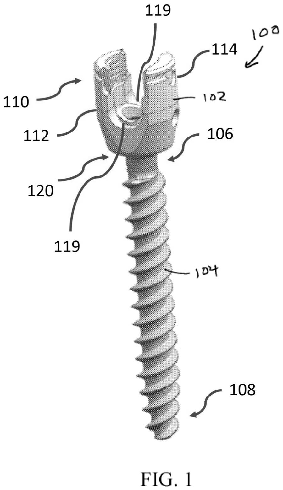
EP 4115826 B1. Drawing as published by the patent office.
GrantedPosterior fixation

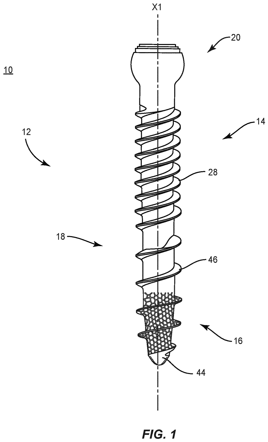
Self-harvesting bone screw with lattice tip

EP 4115826 B1 · granted (B1 published) 14 October 2026

Owner
Warsaw Orthopedic, Inc. (USA; Medtronic)
Applicant
Warsaw Orthopedic, Inc.
Inventors
Dale A. Tempco, Rodney Ray Ballard, Keith E. Miller, William Alan Rezach
Summary and claim

A bone screw with a discontinuous thread and cutting struts that channel removed bone into internal cavities, with a lattice section near the tip. The design is meant to gather autologous bone and encourage fixation.

Main claimProtects a bone screw whose shaft has a discontinuous thread, cavities and circumferential cutting struts that direct removed tissue into those cavities, with a lattice next to the struts.

ContextAdditively manufactured, porous or lattice screw designs are an emerging approach to improving fixation in poor bone.

Read the patent
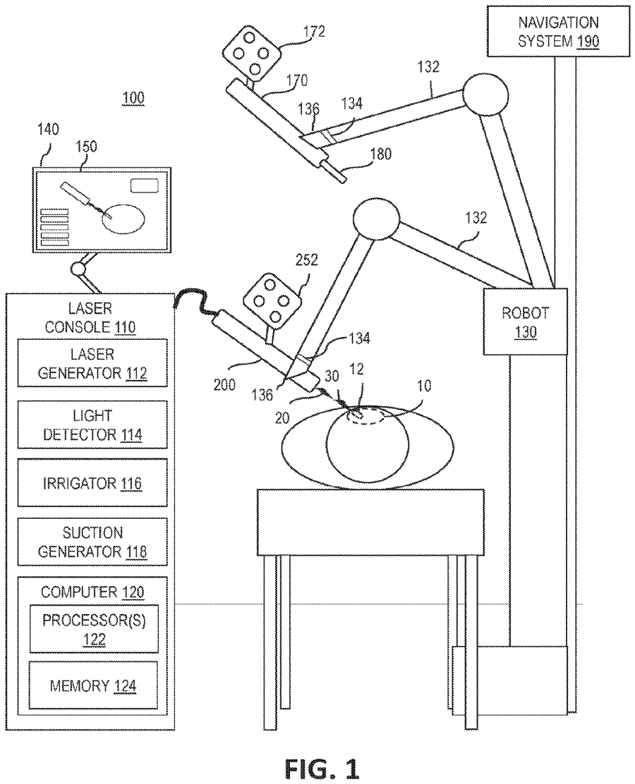
EP 4259028 B1. Drawing as published by the patent office.
GrantedNavigation & robotics

Laser disc preparation through a cannulated screw

EP 4259028 B1 · granted (B1 published) 14 October 2026

Owner
NuVasive, Inc. (USA; Globus Medical)
Applicant
NuVasive, Inc.
Inventors
Eric Finley, Adrien Ponticorvo, Mike Serra, Christopher Nelsen, Robert German, Justin Doose, Danielle Richterkessing, Antonio Ubach, John Love
Summary and claim

A system in which a laser passed through a cannulated screw and driver both removes disc or cartilage tissue without ablating bone and sends interrogating pulses to map the target region. It sits within NuVasive's robotic surgery work.

Main claimProtects an apparatus combining a laser emitting tissue-affecting pulses and interrogating pulses, a light detector for topographic analysis, and a cannulated screw and driver through which the laser extends.

ContextNuVasive is now part of Globus Medical; laser-based disc preparation remains largely experimental.

Read the patent
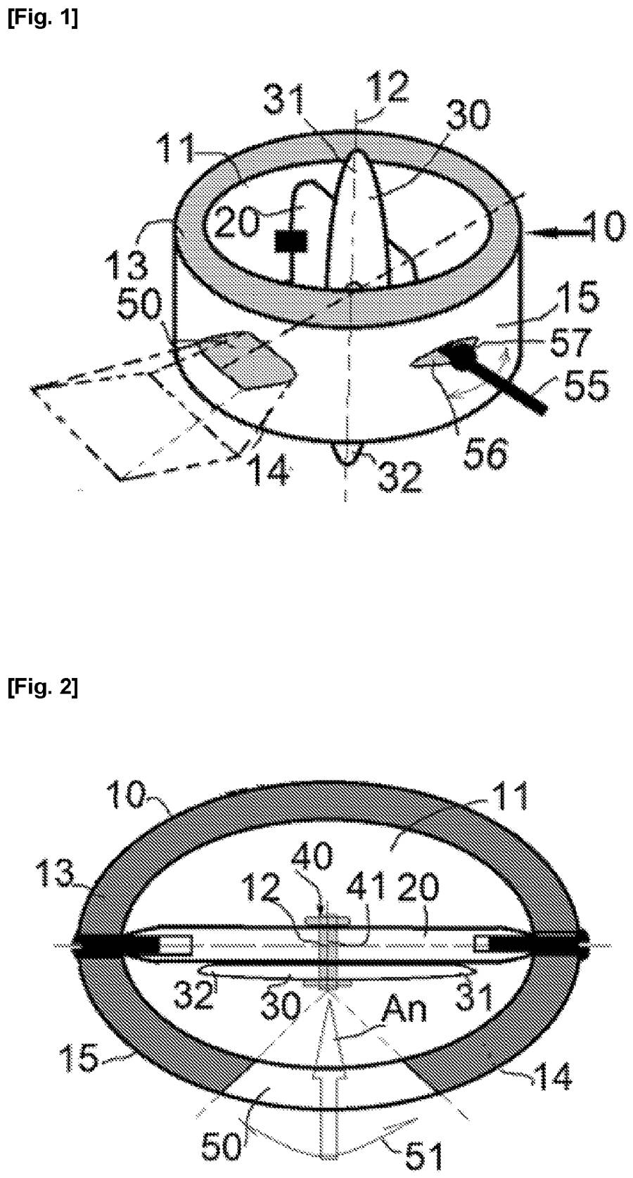
EP 4622601 B1. Drawing as published by the patent office.
GrantedInterbody & cages

Interbody cage with deployable fixation plate

EP 4622601 B1 · granted (B1 published) 14 October 2026

Owner
Hassan Razian (France, individual)
Applicant
Hassan Razian
Inventors
Sam Razian, Salar Razian, Hassan Razian
Summary and claim

An intersomatic cage with a central through-cavity in which a support plate is mounted to anchor the cage to one or both vertebrae. The aim is integrated fixation without a separate plate.

Main claimProtects a solid cage with two parallel bearing faces and a through-cavity perpendicular to them, plus securing means comprising at least one support plate mounted in that cavity.

ContextGranted on a French-language filing; the same applicant also published a related blade-cage application (EP 4817562 A1) this month.

Read the patent
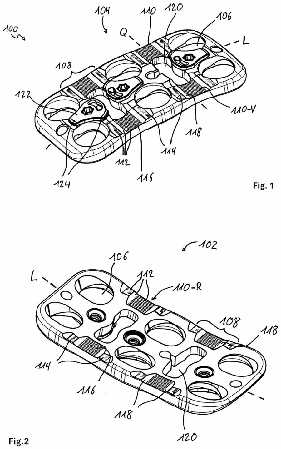
EP 4801391 B1. Drawing as published by the patent office.
GrantedCervical

Cervical plate that can be bent in theatre

EP 4801391 B1 · granted (B1 published) 14 October 2026

Owner
Aesculap AG (Germany; B. Braun)
Applicant
Aesculap AG
Inventors
Andreas Stern
Summary and claim

A vertebral plate, mainly for the cervical spine, with grooved bending zones so the surgeon can adjust its longitudinal curvature intraoperatively with a dedicated bending tool. The patent covers the plate and the plate-plus-tool system.

Main claimProtects a screw-fixed vertebral plate with at least one plastically deformable bending portion carrying a transverse tool-receiving groove for adjusting its curvature during surgery.

ContextGranted on a German-language filing; contouring anterior plates to lordosis is routine but usually done with generic benders.

Read the patent
We could not load this drawing for this issue.
See the drawings on the patent record →
EP 4819929 A1
ApplicationPosterior fixation

Fixation chain that is flexible during placement, then made rigid

EP 4819929 A1 · published 14 October 2026

Owner
Mazor Robotics Ltd. (Israel; Medtronic)
Applicant
Mazor Robotics Ltd.
Inventors
Itay Jerby, Adam D. Glaser, Daniel Paxton Wall, Nir Ofer, Gal Barazani, Ofir Dahan
Summary and claim

A fixation concept in which devices anchored to successive vertebrae are linked by connectors that stay pliable while the vertebrae are positioned and are then made rigid to lock the correction. The background focuses on scoliosis surgery.

Main claim (pending, not yet granted)Per the international (WO 2025/120634) text, covers fixation devices on adjacent vertebrae joined by connectors that switch from flexible during positioning to rigid for fixation.

ContextEuropean phase of WO 2025/120634; an alternative to contouring a rigid rod in deformity correction.

Read the application
EP 4821449 A2. Drawing as published by the patent office.
ApplicationPosterior fixation

Multi-purpose polyaxial pedicle screw

EP 4821449 A2 · published 14 October 2026

Owner
Medos International Sàrl (Switzerland; Johnson & Johnson MedTech/DePuy Synthes)
Applicant
Medos International Sarl
Inventors
Christopher Mickiewicz, Ellen Wasserbauer, Alec Manson, Eric Biester, Paul S. Maguire
Summary and claim

A polyaxial screw designed to serve a wide range of spinal procedures with one implant, with features to ease shank insertion, instrument attachment and rod reduction. The aim is fewer screw variants and lower manufacturing burden.

Main claim (pending, not yet granted)Seeks protection for a polyaxial bone anchor whose U-shaped receiver arms have proximal ends lying on a common circular circumferential path.

ContextDivisional of an earlier DePuy Synthes filing; platform screws that cover open, MIS and deformity use are an industry trend.

Read the application
EP 3810001 B1. Drawing as published by the patent office.
GrantedSI joint

SI joint fusion screw with anti-rotation sleeve

EP 3810001 B1 · granted (B1 published) 7 October 2026

Owner
Life Spine, Inc. (USA)
Applicant
Life Spine, Inc.
Inventors
David T. Mehl, Ali H. Mesiwala
Summary and claim

A sacroiliac fusion implant of a self-tapping, self-harvesting screw coupled to a cylindrical sleeve with anti-rotation features on its outer surface. Bone shavings produced on insertion are retained to aid fusion.

Main claimProtects an SI joint implant comprising a self-tapping screw with self-harvesting cutting geometry and a cylindrical sleeve with external anti-rotation geometry and internal screw-engagement geometry.

ContextEuropean counterpart of the US SI screw patent granted to Life Spine on 4 August 2026.

Read the patent
EP 3982886 B1. Drawing as published by the patent office.
GrantedInterbody & cages

Expandable cage with pivoting supports

EP 3982886 B1 · granted (B1 published) 7 October 2026

Owner
Life Spine, Inc. (USA)
Applicant
Life Spine, Inc.
Inventors
Daniel P. Predick, Madeline Wolters, Michael S. Butler
Summary and claim

An expandable interbody implant with main upper and lower supports plus rotatably coupled pivoting supports, moved by a control assembly with separate control members. This allows height and angle to be adjusted after insertion.

Main claimProtects an expandable implant with upper and lower main supports, upper and lower pivoting supports rotatably coupled to them, and a control assembly with first and second control members governing their movement.

ContextEuropean counterpart in Life Spine's expandable-cage family; a related US modular-endplate patent issued in August.

Read the patent
EP 4120937 B1. Drawing as published by the patent office.
GrantedInstruments & access

Set-screw driver that reduces the rod and stops tulip splay

EP 4120937 B1 · granted (B1 published) 7 October 2026

Owner
Warsaw Orthopedic, Inc. (USA; Medtronic)
Applicant
Warsaw Orthopedic, Inc.
Inventors
Brian A. Butler, William A. Rezach, Molly K. Rice
Summary and claim

A driver for set screws in reduction-type pedicle screws, with a sliding sleeve that braces the screw head walls so they do not splay while the set screw is tightened. A friction fit holds the set screw on the tip.

Main claimProtects a set screw reducer with a shank tip fitting the set screw socket and a sleeve sliding on the shank that prevents receiver sidewall splay during torque transfer, plus a frictional retention structure.

ContextTulip splay during final tightening is a known cause of construct failure, especially when reducing rods.

Read the patent
EP 4543333 B1. Drawing as published by the patent office.
GrantedInstruments & access

Rack distractor for segments with uneven pedicles

EP 4543333 B1 · granted (B1 published) 7 October 2026

Owner
Warsaw Orthopedic, Inc. (USA; Medtronic)
Applicant
Warsaw Orthopedic, Inc.
Inventors
Loic Josse
Summary and claim

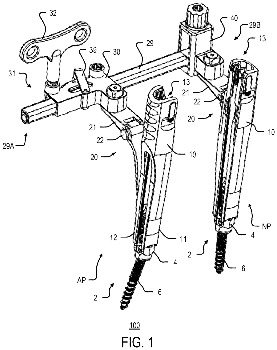
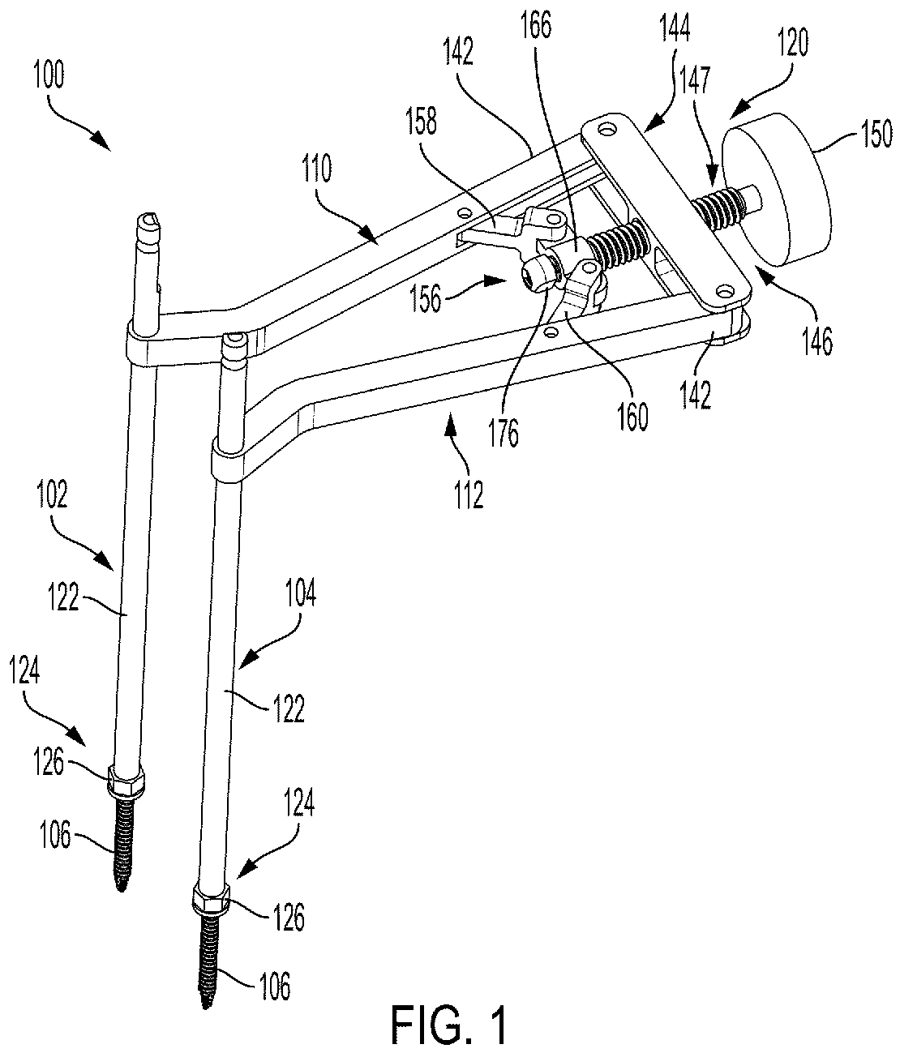
A rack-and-pinion compressor-distractor whose two towers attach to screws and can accommodate pedicles at different heights or offsets. A ratchet and pawl hold the position while the segment is adjusted.

Main claimProtects a system with a splined rack arm, a sliding body with geared actuator and ratchet pawl, and two connection towers mounted transversely on the rack and sliding body.

ContextSegmental distraction and compression through screw towers is standard in MIS TLIF and deformity work.

Read the patent
EP 4759251 B1. Drawing as published by the patent office.
GrantedPosterior fixation

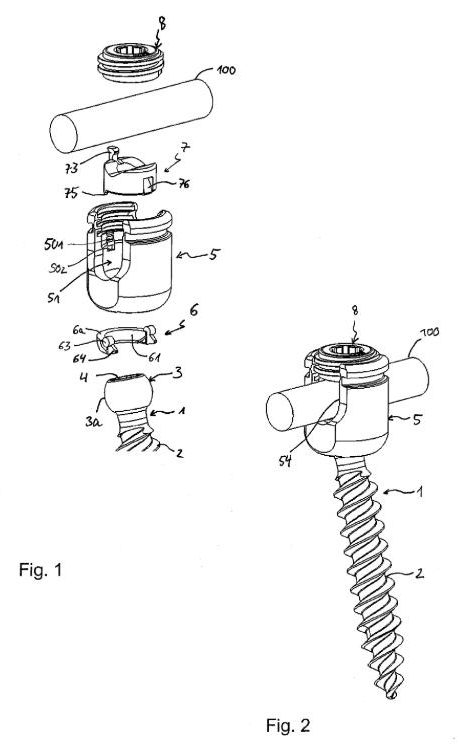
Modular pedicle screw with adjustable angulation limits

EP 4759251 B1 · granted (B1 published) 7 October 2026

Owner
Biedermann Technologies GmbH & Co. KG (Germany)
Applicant
Biedermann Technologies GmbH & Co. KG
Inventors
Lutz Biedermann, Timo Biedermann
Summary and claim

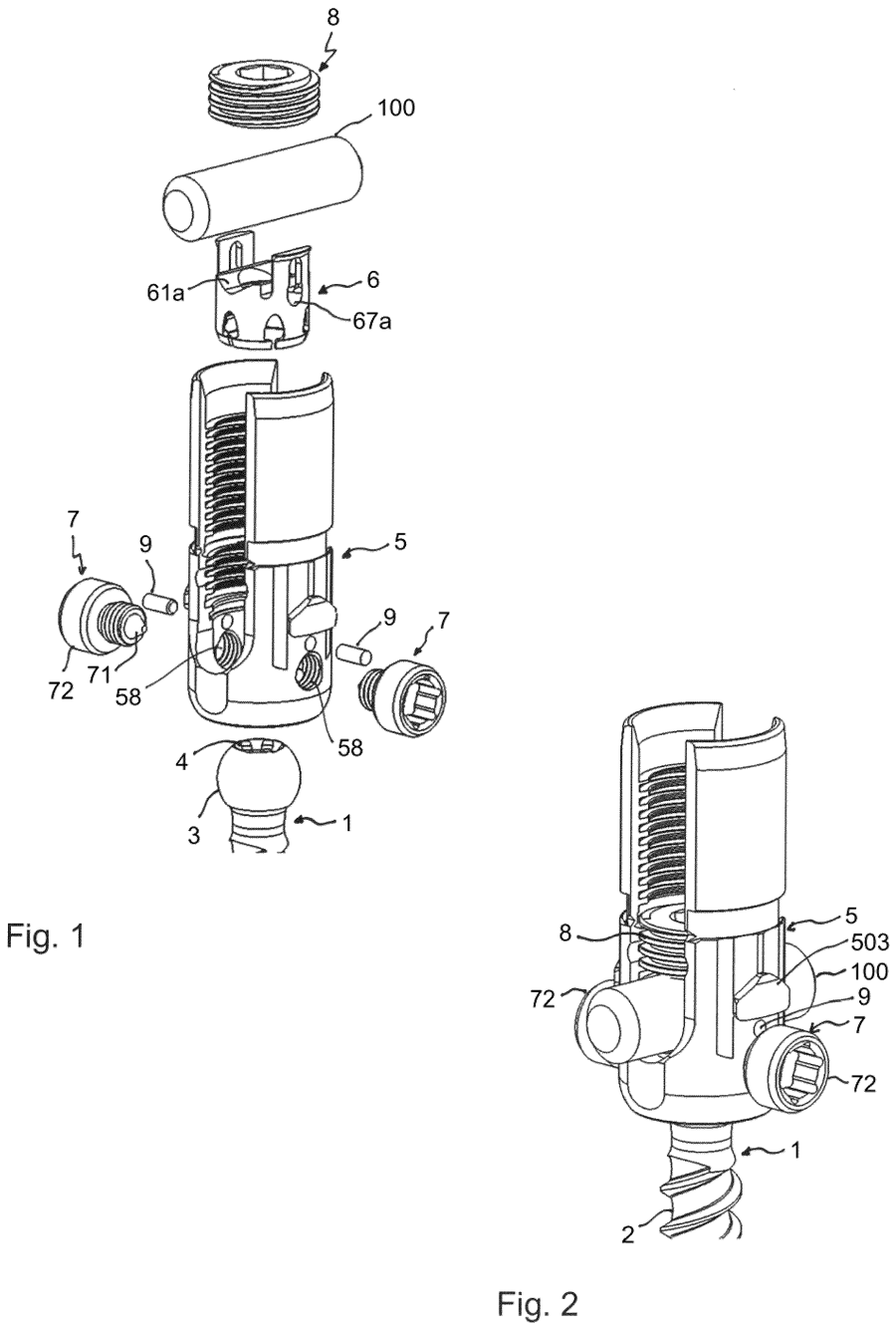
A modular polyaxial screw whose receiving part has threaded side holes for insertable restriction elements that limit or shape the head's angulation. One screw platform can thus be adapted to different clinical needs.

Main claimProtects a rod-coupling bone anchor whose receiving part has at least one internally threaded transverse hole accepting an externally threaded restriction element, together with a pressure element acting on the head.

ContextBiedermann (Donaueschingen) designs many of the polyaxial screw heads licensed across the industry.

Read the patent
We could not load this drawing for this issue.
See the drawings on the patent record →
EP 4815878 A1
ApplicationBiologics

Interlocking granules to fill vertebral bone voids

EP 4815878 A1 · published 7 October 2026

Owner
Kyocera Medical Technologies, Inc. (USA)
Applicant
Kyocera Medical Technologies, Inc.
Inventors
Dennis Ty, Trace Cawley, Scott Rucker
Summary and claim

Small engineered granules (about 1 to 10 mm) of bone, metal, ceramic or polymer that interlock to fill bone voids and support ingrowth while resisting migration. Kyphoplasty and vertebroplasty are named as example uses.

Main claim (pending, not yet granted)Per the international (WO 2025/117313) claims, protects a granule of 1-10 mm whose body has struts, a truss, shell, lobes or a roughened surface allowing it to interlock with neighbours and support bone ingrowth.

ContextEuropean phase of WO 2025/117313; the claims are not limited to the spine.

Read the application
EP 4817532 A2. Drawing as published by the patent office.
ApplicationInstruments & access

Pin-based vertebral distractor-retractor

EP 4817532 A2 · published 7 October 2026

Owner
Shukla Medical (USA)
Applicant
Shukla Medical
Inventors
Mitchell Kiska, Osama Ahmed
Summary and claim

A vertebral retractor built around two threaded distraction pins held by arms that an adjuster assembly moves apart or together. It is intended to hold the vertebrae apart during disc-space work.

Main claim (pending, not yet granted)Seeks protection for a retractor with two threaded-tip distraction pins, an arm securing each pin and an adjuster assembly that changes the arms' relative position.

ContextCaspar-type pin distraction is standard in anterior cervical surgery; this is a variant from an instrument maker known for implant-removal tools.

Read the application
EP 4817540 A1. Drawing as published by the patent office.
ApplicationInterbody & cages

Curved blade anchor that locks an expandable cage to the vertebrae

EP 4817540 A1 · published 7 October 2026

Owner
Globus Medical, Inc. (USA)
Applicant
Globus Medical, Inc.
Inventors
Matthew Bakey, Jason Zappacosta
Summary and claim

A curved-blade anchor with a spherical head that fixes an expandable interbody device to the adjacent vertebrae. A single impactor engages the head with a quarter-turn connection and can drive anchors straight or angled, including under navigation.

Main claim (pending, not yet granted)Seeks protection for an anchor whose spherical head has a non-threaded vertical slot opening into an internal spherical pocket, with a raised bump beneath the slot to thicken the wall.

ContextBlade-type anchors are a common way to give stand-alone cages integrated fixation without screws.

Read the application
EP 4817562 A1. Drawing as published by the patent office.
ApplicationInterbody & cages

Disc-shaped cage with rotating locking blade

EP 4817562 A1 · published 7 October 2026

Owner
Hassan Razian (France, individual applicant)
Applicant
Hassan Razian
Inventors
Hassan Razian
Summary and claim

An intersomatic cage carrying a blade on a rotating shaft that swings out of the cage to grip a vertebra. A small deformed lug on the blade tip snaps over the cage wall to hold the blade in its deployed position.

Main claim (pending, not yet granted)Seeks protection for a disc-shaped cage with a blade mounted off-centre on a rotating shaft so that it moves from fully inside the cage profile to protruding into the vertebra.

ContextFiled in French by an independent French inventor; one of several deployable-blade stand-alone cage concepts.

Read the application
EP 4817563 A2. Drawing as published by the patent office.
ApplicationNavigation & robotics

Calibrating an interbody cage for navigation with a tracked pointer

EP 4817563 A2 · published 7 October 2026

Owner
Brainlab SE (Germany)
Applicant
Brainlab SE
Inventors
Thomas Drexl, Dimitrij Surmeli, Amar Husejic
Summary and claim

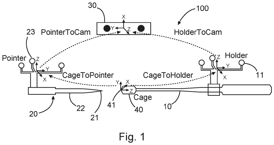
A navigation workflow that builds a virtual model of a spinal cage by touching its tip and end with a tracked pointer and laying the pointer shaft along its sides, while the cage sits on a tracked holder. This lets the cage be shown accurately on navigation without breaking sterility.

Main claim (pending, not yet granted)Seeks protection for a cage calibration system that records the cage tip and end points with the pointer tip and at least one side axis with the pointer shaft, then computes a calibrated virtual cage model.

ContextDivisional of an earlier Brainlab application; navigated cage placement extends navigation beyond pedicle screws.

Read the application
We could not load this drawing for this issue.
See the drawings on the patent record →
EP 4817564 A1
ApplicationInstruments & access

Screw-driven jaw extractor for removing spinal cages

EP 4817564 A1 · published 7 October 2026

Owner
Shukla Medical (USA)
Applicant
Shukla Medical
Summary and claim

An extractor for removing an interbody cage, in which a threaded adjuster drives a shaft that closes a pair of jaws onto the implant. It is aimed at controlled cage removal instead of free-hand pliers.

Main claim (pending, not yet granted)Per the abstract (claims not read), covers a housing, a shaft with a threaded end moving within it, jaws on the shaft tip and a threaded adjuster that moves the shaft and jaws between positions.

ContextRevision surgery for failed or migrated cages relies on dedicated removal instruments.

Read the application

Europe, September 2026

Earlier in 2026

15 European patent applications published by the EPO in September 2026, found by spine classification codes. All are applications; European grants are not yet covered.

Screws and rods

FIGS. 1–2, EP 4799579 A1. Drawing via Espacenet.
ApplicationPedicle screwUniplanar

Uniplanar bone anchor

EP 4799579 A1 · published 2 September 2026

Owner
Biedermann Technologies (Germany)
Applicant
Biedermann Technologies GmbH & Co. KG
Inventors
Lutz Biedermann, Timo Biedermann, Berthold Dannecker
Summary and claim

A polyaxial-style screw whose head can only swing in one plane. A pressure element grips the head from the side and the top, and a ridge inside the receiving part limits the movement.

Main claim (pending, not yet granted)A protrusion on the inner wall of the receiving part bears on a matching surface of the screw head, restricting pivoting to a single plane.

ContextUniplanar screws are widely used in deformity correction for derotation. Novelty here lies in the mechanism, not the concept.

Read the application
FIGS. 1–2, EP 4813326 A1. Drawing via Espacenet.
ApplicationPedicle screwModular

Bottom-loading polyaxial coupling

EP 4813326 A1 · published 30 September 2026

Owner
Biedermann Technologies (Germany)
Applicant
Biedermann Technologies GmbH & Co. KG
Inventors
Lutz Biedermann, Bernd Fischer
Summary and claim

A tulip that can be attached to a screw head after the screw is placed. The head enters through an opening at the bottom, and a retainer ring completes the seat around it.

Main claim (pending, not yet granted)The receiving part and a separate retainer element each provide part of the seat, and together they form a socket in which the head can pivot.

ContextBottom-loading tulips let the surgeon place screw shanks first. Several companies sell modular systems of this kind.

Read the application
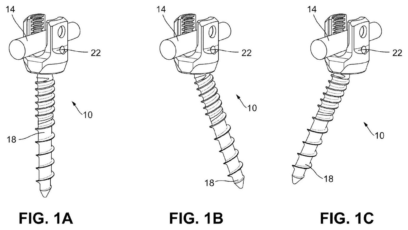
FIGS. 1A–1C, WO 2025/093991 A1, the international version of this application (sheet rotated to read upright). Drawing via Espacenet.
ApplicationPedicle screw

Crown locking mechanism for spinal screw

EP 4801389 A1 · published 9 September 2026

Owner
Medtronic
Applicant
Warsaw Orthopedic, Inc.
Inventors
William Alan Rezach, Anela Camdzic Holdaway, Shane Lars Riding
Summary and claim

A spring-loaded catch in the screw’s connector body snaps into a slot on the internal crown, holding the crown in place along the screw’s axis.

Main claim (pending, not yet granted)A biasing member sits in a bore of the connector body. When released it pushes into the central opening and engages the crown’s slot, so the crown cannot move up or down.

ContextFiled on the same day and by the same lead inventor as the adjustable screw below; the two share their drawings.

Read the application
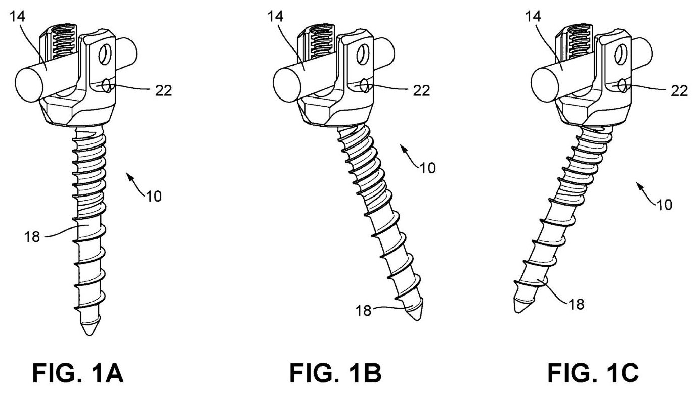
FIGS. 1A–1C, WO 2025/093995 A1, the international version of this application (sheet rotated to read upright). Drawing via Espacenet.
ApplicationPedicle screwFavoured angle

Adjustable spinal screw with off-centre seat

EP 4801390 A1 · published 9 September 2026

Owner
Medtronic
Applicant
Warsaw Orthopedic, Inc.
Inventors
William Allen Rezach
Summary and claim

A polyaxial screw whose head sits in an off-centre (eccentric) base connector inside the tulip.

Main claim (pending, not yet granted)An eccentric base connector in the bottom of the connector body has an off-centre opening for the screw head and a second opening for the crown.

ContextPlacing the head off-centre changes where the screw can angle. Favoured-angle screws exist; this is a different way of achieving that.

Read the application
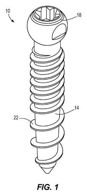
FIG. 1, WO 2025/088550 A1, the international version of this application. Drawing via Espacenet.
ApplicationPedicle screwCarbon/PEEK

Non-metallic spinal screw

EP 4798092 A1 · published 2 September 2026

Owner
Medtronic
Applicant
Warsaw Orthopedic, Inc.
Inventors
Joel Patrick Bales
Summary and claim

A screw made without metal: a PEEK core wrapped in a carbon-fibre layer that also forms the thread.

Main claim (pending, not yet granted)A PEEK core at least partly encapsulated by a carbon-fibre reinforcement layer; a dependent claim adds that the layer forms the outer thread of a spinal screw.

ContextCarbon-fibre/PEEK implants are used mainly in spinal oncology, where they reduce imaging artefacts and help radiotherapy planning.

Read the application
FIG. 1, EP 4813327 A1. Drawing via Espacenet.
ApplicationRodComposite

Layered fibre spinal rod with clamp markings

EP 4813327 A1 · published 30 September 2026

Owner
Globeride (Japan), maker of Daiwa fishing tackle
Applicant
Globeride, Inc.
Inventors
Katsuhiro Oikawa, Hiroshi Kusaka, Harunobu Kusumoto
Summary and claim

A rod built from fibre layers laminated around its axis, marked to show where the screw clamps should grip.

Main claim (pending, not yet granted)The markings indicate clamping points where the clamping force runs across the fibre layers rather than along them, so the clamp does not split the laminate.

ContextGloberide’s core business is carbon-fibre fishing rods, so this is an unusual entrant applying composite know-how to spinal rods.

Read the application
FIGS. 1–3, EP 4809949 A1. Drawing via Espacenet.
ApplicationScrewIndividual inventor

Double-threaded spinal fixation screw

EP 4809949 A1 · published 23 September 2026

Owner
Janez Mohar (Slovenia)
Applicant
Janez Mohar (individual)
Inventors
Janez Mohar
Summary and claim

A screw threaded at both ends with a smooth shaft of constant diameter between them, offered as a kit with a connector to the rod.

Main claim (pending, not yet granted)Both threaded ends have the same thread pitch, with an unthreaded section of constant diameter between them.

ContextAn application from an individual inventor, which is rare in this field. How the screw is meant to be placed is set out in the description.

Read the application

Interbody and vertebral body replacement

FIG. 1, EP 4803049 A2. Drawing via Espacenet.
ApplicationInterbodyExpandable

Expandable cage

EP 4803049 A2 · published 9 September 2026

Owner
Johnson & Johnson (DePuy Synthes)
Applicant
Medos International SARL
Inventors
Connor Engstrom
Summary and claim

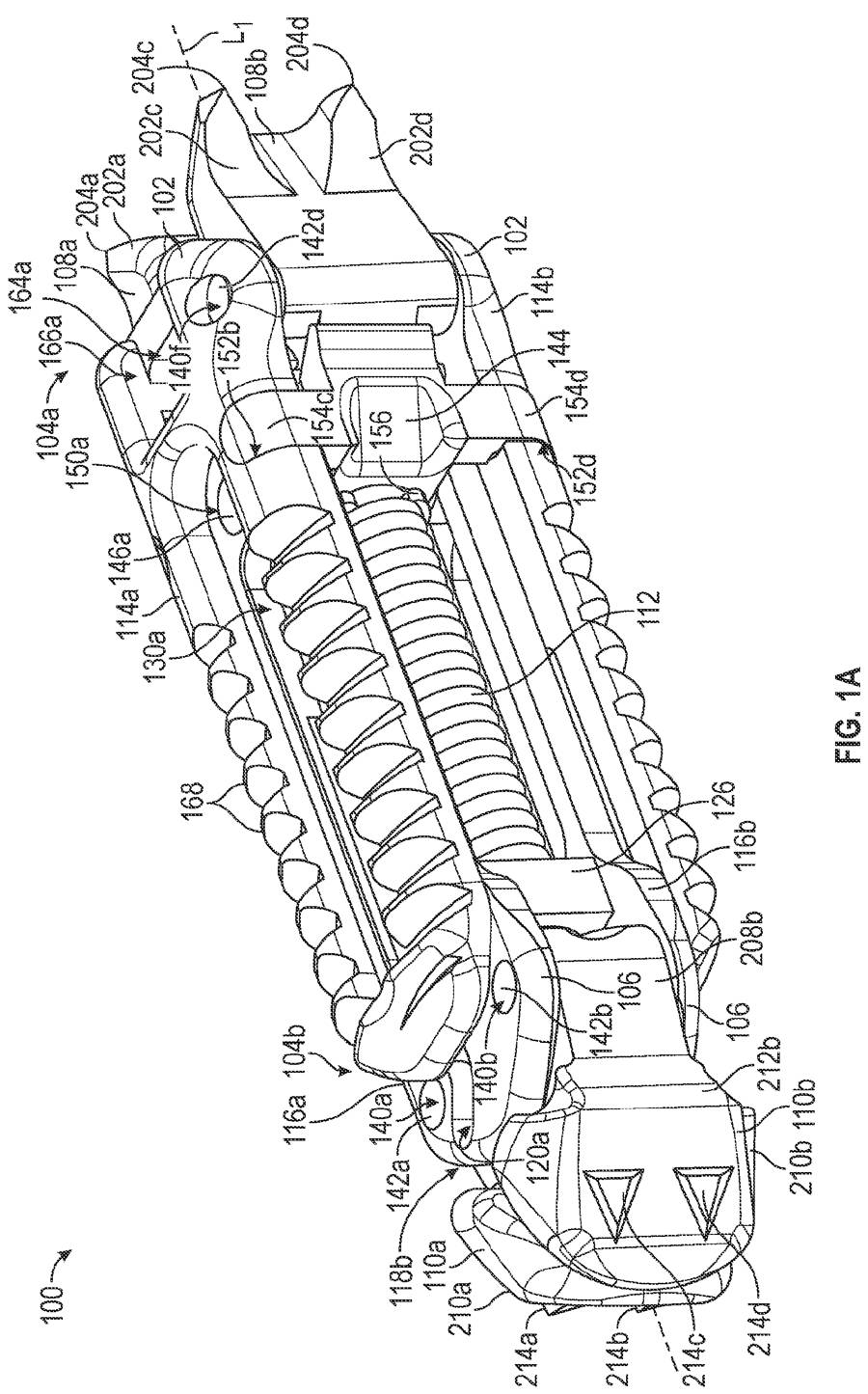
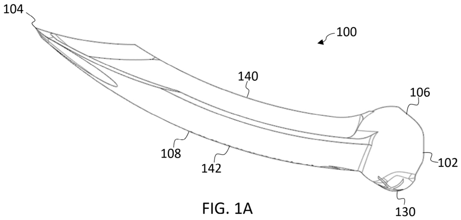
An intervertebral cage that expands in height. Wedges riding on inclined ramps push the two plates apart in two stages when a drive shaft is turned.

Main claim (pending, not yet granted)An expansion wedge made of two members, each coupled to one plate, with a drive shaft passing through bores in both.

ContextThis is a divisional of a family first filed in 2017, so the technology itself is not new; it is a fresh set of claims on an older invention.

Read the application
FIG. 1, EP 4806397 A2. Drawing via Espacenet.
ApplicationCorpectomyExpandable

Expandable vertebral body replacement

EP 4806397 A2 · published 16 September 2026

Owner
Alphatec Spine
Applicant
Alphatec Spine, Inc.
Inventors
Parker Smith, Steven Leong, Jared Beach, Thomas Hackathorn, Scott Robinson
Summary and claim

A telescoping vertebral body replacement: an inner column threads out of an outer column, driven by an expansion ring, with modular endplates.

Main claim (pending, not yet granted)The endplates are held to the columns by captive set screws that cannot fall out, so endplates can be exchanged.

ContextExpandable corpectomy cages are well established. The claim focuses on how modular endplates attach.

Read the application
FIGS. 1A–1B, EP 4803311 A2. Drawing via Espacenet.
ApplicationInterbodyBioactive

Piezoelectric truss implant

EP 4803311 A2 · published 9 September 2026

Owner
4WEB Medical
Applicant
4WEB, Inc.
Inventors
Jessee Hunt, Cameron N. Carmody, Timothy Ganey
Summary and claim

An open truss implant whose struts are partly made of a piezoelectric hydroxyapatite composite, which produces small electrical charges under load.

Main claim (pending, not yet granted)A web of struts joined at nodes, some struts formed at least partly of a piezoelectric hydroxyapatite composite.

ContextElectrical stimulation of bone healing is a long-standing idea. Building it into the implant material is the new angle. This is a divisional of a 2019 family.

Read the application
FIGS. 1A–1B, WO 2025/090846 A1, the international version of this application. Drawing via Espacenet.
ApplicationInterbodyFixation

Anchor guide for truss implants

EP 4798085 A1 · published 2 September 2026

Owner
4WEB Medical
Applicant
4WEB, LLC
Inventors
Jessee Hunt, David Knox
Summary and claim

A guide fixed to the implant surface steers bone anchors through the implant body into the adjacent bone, turning a truss cage into a stand-alone device.

Main claim (pending, not yet granted)A guide body on the implant defines anchor pathways; anchors pass through part of the implant body to enter the bone.

ContextIntegrated fixation for stand-alone cages is common. This adapts it to an open truss structure.

Read the application

Sacroiliac joint

FIG. 1, WO 2025/101203 A1, the international version of this application (sheet rotated to read upright). Drawing via Espacenet.
ApplicationSI jointFusion

Threaded SI-joint fusion implant with lattice section

EP 4804936 A1 · published 16 September 2026

Owner
Spinal Simplicity
Applicant
Spinal Simplicity, LLC
Inventors
Todd Moseley, Luke Luallin, Adam Rogers, Christian Aragonez, Jeff Slover, Tony Hartlage
Summary and claim

A cannulated, threaded implant for fusing the sacroiliac joint, with an insertion instrument.

Main claim (pending, not yet granted)A central section where a porous lattice lies between the solid core around the cannula and the external thread. Espacenet shows the claims of the international version, as the European claims are not yet available.

ContextThreaded and triangular SI-joint implants compete in a growing market; a lattice section aims at ingrowth.

Read the application

Planning and software

FIG. 1, EP 4809957 A1 (sheet rotated to read upright). Drawing via Espacenet.
ApplicationRod bendingPlanning

Automated in-theatre forming of patient-specific rods

EP 4809957 A1 · published 23 September 2026

Owner
Blue Bend Medical (Canada)
Applicant
Blue Bend Medical Technologies Ltd.
Inventors
Davoud Karmi, Stephen Lewis, Christopher Nielson
Summary and claim

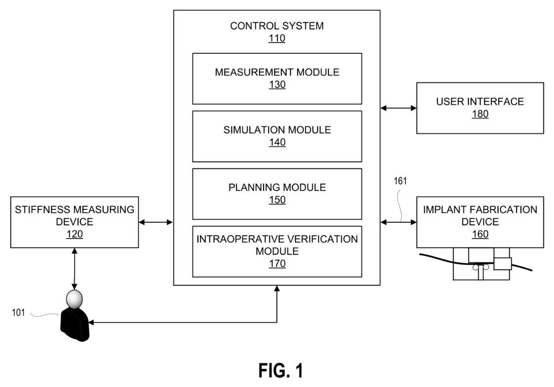
Software takes the patient’s spine imaging and a stiffness measurement, plans the correction, and drives a device that forms a patient-specific rod during surgery.

Main claim (pending, not yet granted)A system that derives spinopelvic parameters from imaging of the patient’s spine and uses them to form the rod automatically during the operation.

ContextPre-bent patient-specific rods are made in factories today. Forming them in the operating room shortens the loop between plan and implant.

Read the application
Figure 1, EP 4803025 A1. Drawing via Espacenet.
ApplicationSimulationPlanning

Live finite-element model of implant–bone interaction

EP 4803025 A1 · published 9 September 2026

Owner
Spinevision (France)
Applicant
Spinevision
Inventors
Renaud Duchenes, Hugo Dumesnil, Antony Rouhban
Summary and claim

Software builds a finite-element model of the implant system acting on the patient’s spine and keeps updating it from signals the instruments send during surgery.

Main claim (pending, not yet granted)A generation module builds the finite-element model, a reception module repeatedly receives signals from the surgical system, and an adaptation module updates the model from them.

ContextPatient-specific simulation is usually done before surgery. Feeding it live data from the instruments is the step this application claims.

Read the application
FIGS. 1–2, WO 2025/109013 A1, the international version of this application. Drawing via Espacenet.
ApplicationPatient-specificDesign

Designing patient-specific, structurally optimised implants

EP 4812123 A1 · published 30 September 2026

Owner
ETH Zürich, DTU and Schulthess Klinik (academic)
Applicant
ETH Zürich, Technical University of Denmark, Schulthess Klinik
Inventors
Thijs Smit, Benedikt Helgason, Niels Aage, Stephen Ferguson, Daniel Haschtmann
Summary and claim

A computer method that designs an implant to fit the patient’s bone surfaces and then optimises its internal structure for strength and for manufacture.

Main claim (pending, not yet granted)A computer-implemented method that defines the bone surfaces in a patient-specific model of the implant site and generates an implant model fitted to them and structurally optimised for its manufacturing method.

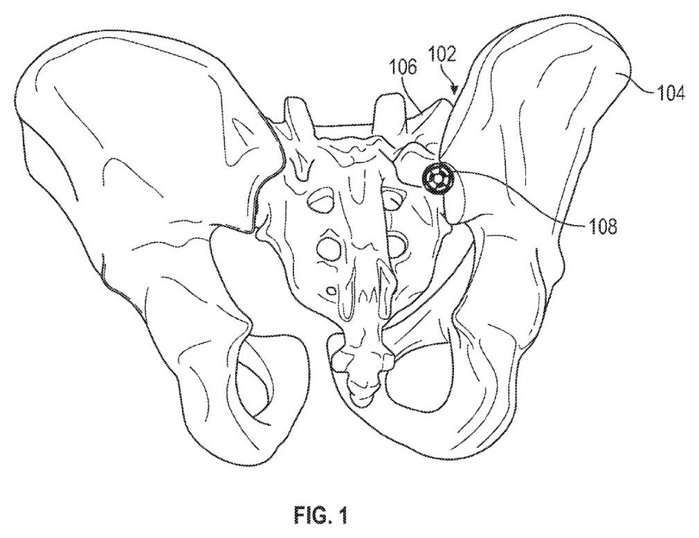
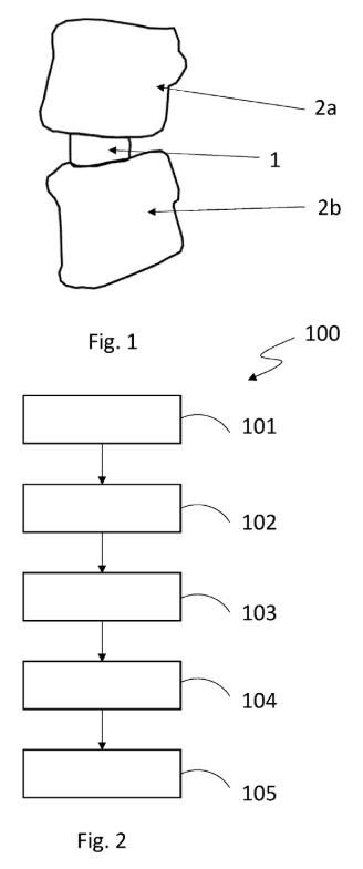
ContextA Swiss–Danish academic and clinical collaboration; the drawing shows an interbody implant between two vertebrae.

Read the application

Understanding patents: a short guide

Not legal or regulatory advice. This guide is general information, not legal or regulatory advice. Patent and medical device rules change and differ between countries; for decisions about a specific invention or product, consult a qualified patent attorney or regulatory specialist.

From application to grant

United States. A provisional application needs no formal claims, is not examined and lapses after 12 months unless a full (non-provisional) application claiming it is filed. That application is normally published shortly after 18 months from the earliest filing date (kind code A1), then examined. A grant is coded B2 if previously published, B1 if not. The term generally ends 20 years after the US filing date, and maintenance fees fall due 3.5, 7.5 and 11.5 years after grant; unpaid, the patent lapses.

Europe. The European Patent Office (EPO) issues a search report and publishes the application at 18 months from filing or priority (A1 with the search report, A2 without, A3 for a later search report). Examination must be requested within six months of the search report's publication. Grant is published as B1, followed by a nine-month opposition window. The EPO puts the whole procedure at about three to five years. The patent is then validated country by country or, since 1 June 2023, registered as a Unitary Patent (within one month of grant), currently covering 18 EU states.

International (PCT). WIPO publishes PCT applications (WO) at about 18 months. They never become patents themselves: national or regional offices decide, usually after entry by 30 months from priority.

Sources: USPTO: Provisional application for patent · 35 U.S.C. 122 (publication of applications) · 35 U.S.C. 154 (rights and term) · USPTO: Kind codes · USPTO: Maintain your patent · USPTO: Patents pendency dashboard (current waiting times) · EPO: European patent grant process (overview chart) · EPO: How long does the grant procedure take? · EPO Guidelines A-VI 2.2: time limit for request for examination · EPO: Oppositions · EPO: Kind codes of EP publications · EPO: Unitary Patent · EPO Official Journal 2023, Supplementary publication 3 (Unitary Patent from 1 June 2023) · WIPO: PCT frequently asked questions

What application versus granted means

A published patent application is a request for protection, not protection itself. Its claims, the numbered sentences that define what the applicant wants to own, are often narrowed, rewritten or refused during examination, and many applications are abandoned. Reading an application tells you what someone hopes to protect, not what they will end up with.

Only a granted patent gives enforceable rights, and those rights are to exclude others from making, using, selling or importing the claimed invention. Even a grant can still be challenged, for example in a European opposition within nine months. Rights are also territorial: a US patent has effect only in the United States, and a European patent only in the countries where it is validated or covered by unitary effect. A device patented in one country may be free to use in another.

  • Kind codes ending in A (for example US A1, EP A1) usually mean a published application.
  • Kind codes ending in B (US B1/B2, EP B1) mean a granted patent.
  • WO publications are international applications, never granted patents.

Sources: 35 U.S.C. 154 (right to exclude in the United States) · EPO Guide for applicants: effect of a European patent and term · EPO: Oppositions · USPTO: Kind codes · WIPO: PCT frequently asked questions

Classification codes

Every patent document is labelled with technical classification codes so that examiners and searchers can find related inventions regardless of language or wording. The International Patent Classification (IPC) is maintained by WIPO and used by patent offices worldwide. The Cooperative Patent Classification (CPC) is a more detailed extension of the IPC, run jointly by the EPO and the USPTO; its codes look the same but have extra subdivisions.

A code reads from broad to narrow. In A61B 17/7032, 'A61B' is the subclass (diagnosis and surgery), '17/70' the group for spinal positioners and stabilisers, and '7032' a subgroup (screws or hooks with a U-shaped head through which rods pass, the familiar tulip-head pedicle screw). A single patent usually carries several codes, and codes beginning with an extra '20', such as A61B 2017/..., are additional indexing codes. The table below gives the spine-relevant codes used on this page, with titles checked against the CPC scheme.

Spine-relevant classification codes
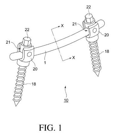
CodeWhat it covers
A61B 17/70Spinal positioners or stabilisers: the main group for spinal fixation implants
A61B 17/7001Screws or hooks combined with rods or other longitudinal elements (pedicle screw and rod constructs)
A61B 17/7002Longitudinal elements, for example spinal rods
A61B 17/7032Screws or hooks with a U-shaped head that the rod passes through (tulip-head screws)
A61B 17/7035Screws whose head can pivot on the shank (polyaxial screws)
A61B 17/7049Connectors linking rods together, for example cross-links
A61B 17/7059Cortical plates for the spine, for example anterior cervical plates
A61B 17/7062Devices acting on or attached to spinous processes, facets or ribs, for example interspinous spacers and facet devices
A61B 17/7071Implants for expanding or repairing the vertebral arch or placed between laminae or pedicles (for example laminoplasty implants)
A61B 17/7074Tools specially made for spinal fixation operations
A61B 17/7083Tools for guiding or inserting rods, connectors or tethers (often minimally invasive rod insertion)
A61B 17/7091Tools for applying, tightening or removing the locking elements between rod and screw (set-screw drivers)
A61B 17/7097Stabilisers filled with fluid in an implant, for example a balloon, and devices to insert or fill them
A61B 17/1671Drills, chisels and similar bone-cutting instruments for the spine
A61B 17/1757Drill and wire guides for the spine, for example pedicle screw trajectory guides
A61B 17/88Instruments and methods for implanting or removing internal or external fixation devices
A61B 17/8802Equipment for handling bone cement or other fluid fillers (for example vertebroplasty)
A61B 17/885Tools for expanding or compacting bone or discs or cavities in them (for example balloon kyphoplasty tools)
A61F 2/44Joint prostheses for the spine, for example vertebrae or spinal discs
A61F 2/442Intervertebral disc prostheses (disc replacements)
A61F 2/4425Disc prostheses made of articulated components (for example ball-and-socket disc replacements)
A61F 2/4455Implants for fusing vertebral bodies, for example interbody fusion cages
A61F 2/4611Instruments for inserting or removing spinal prostheses, including cage inserters
A61B 34/10Computer-aided planning, simulation or modelling of operations
A61B 34/20Surgical navigation and tracking or guiding of instruments
A61B 34/30Surgical robots
A61B 90/36Imaging or illumination devices for surgery not covered elsewhere, including augmented reality
A61B 90/37Surgical systems showing images on a monitor during the operation, for example intraoperative fluoroscopy or CT
A61L 27/00Materials for implants and grafts, or for coating them
A61L 27/06Titanium or titanium alloys as implant materials
G16H 20/40Health informatics for surgery and other mechanical, radiation or invasive therapies
G16H 30/40Software for processing medical images
G16H 50/50Computer simulation or modelling of medical disorders
A61N 1/36062Spinal cord stimulation (under A61N 1/36, electrical stimulation)
A61N 1/0551Spinal or peripheral nerve electrodes

Sources: Cooperative Patent Classification (official site) · WIPO: International Patent Classification (IPC) · CPC scheme A61B (USPTO), group 17/70 · CPC scheme A61F (USPTO), group 2/44 · Espacenet CPC browser (EPO)

A patent is not a regulatory approval

A patent protects an invention: it rewards novelty and inventiveness by letting the owner stop others from using the claimed idea for a limited time. It is granted on the basis of documents, without any testing of the device, and says nothing about whether the device is safe, whether it works in patients, or whether it can be sold.

Market access is a separate legal process. In the United States, the Food and Drug Administration (FDA) clears or approves devices; in the European Union, a notified body certifies conformity under the Medical Device Regulation before CE marking; in Great Britain, the MHRA oversees the market. A product can be on sale without any patent, and a patent can exist for a device that is never made. Many patented ideas never reach the operating theatre, because of cost, test results, regulatory hurdles or simple commercial choices. Reading Patent Watch is therefore a view of where development effort is going, not a list of available products.

Sources: 35 U.S.C. 154 (what a patent grants) · FDA: Premarket notification 510(k) · Regulation (EU) 2017/745 on medical devices (EUR-Lex) · GOV.UK: Government confirms indefinite recognition of CE marked medical devices

The patent journey: from idea to clinical use

Typical steps, often overlapping: idea; invention disclosure; first (often provisional) filing to secure a priority date; prototypes; bench testing, for example ASTM F1717 (spinal implant constructs in a vertebrectomy model) and ASTM F2077 (intervertebral body fusion devices); design controls within a quality system; regulatory submission. Overall timelines vary widely and no official average exists.

United States. Pedicle screw systems and interbody fusion devices are class II and usually go through a 510(k), showing substantial equivalence to a device already on the market; the FDA goal is a decision within 90 FDA days (excluding time on hold). Fusion devices containing a biologic such as BMP are class III. Novel devices without a predicate may use De Novo (goal 150 FDA days). Class III devices such as artificial discs need premarket approval (PMA), usually after a clinical trial under an investigational device exemption (IDE); the review goal is 180 FDA days, or 320 with an advisory panel.

European Union. Under the MDR (EU) 2017/745, Annex VIII Rule 8 places spinal disc replacements and implants in contact with the spinal column in class III, except components such as screws, wedges, plates and instruments; notified bodies note the wording is open to interpretation, with fusion devices possibly remaining class IIb. A notified body assesses technical documentation, clinical evaluation and the quality system before CE marking. In a 2024 survey, 44% of new MDR certificates took 13–18 months from application and 24% longer.

United Kingdom. Great Britain has its own UKCA mark under MHRA oversight, and the government has confirmed that CE-marked devices will continue to be accepted on a long-term basis.

Sources: ASTM F1717-21: Spinal implant constructs in a vertebrectomy model · ASTM F2077-22: Intervertebral body fusion devices · 21 CFR 888.3070 Thoracolumbosacral pedicle screw system (eCFR) · 21 CFR 888.3080 Intervertebral body fusion device (eCFR) · FDA: Premarket notification 510(k) · FDA: 510(k) submission process (90 FDA days) · FDA: De Novo classification request · FDA: Premarket approval (PMA) · FDA: MDUFA V performance goals FY2023–2027 · Regulation (EU) 2017/745 on medical devices (EUR-Lex) · Joint notified bodies paper: MDR Rule 8 classification of spinal implants · Team-NB Medical Device Survey 2024 (certification times) · GOV.UK: Government confirms indefinite recognition of CE marked medical devices

Spinal Frontiers is published by NSpine Limited, registered in England and Wales (company no. 08362634), 14 Park Row, Nottingham NG1 6GR, United Kingdom. Every item is summarised in our own words and links to its original source. Listings are a selection made at NSpine's editorial discretion and are not exhaustive; inclusion is not an endorsement, and omission implies nothing. Sponsors and advertisers have no influence on what we cover. Nothing here is medical, legal or financial advice. Spotted an error or a broken link? Email spinalfrontiers@nspine.com, or use the feedback page.
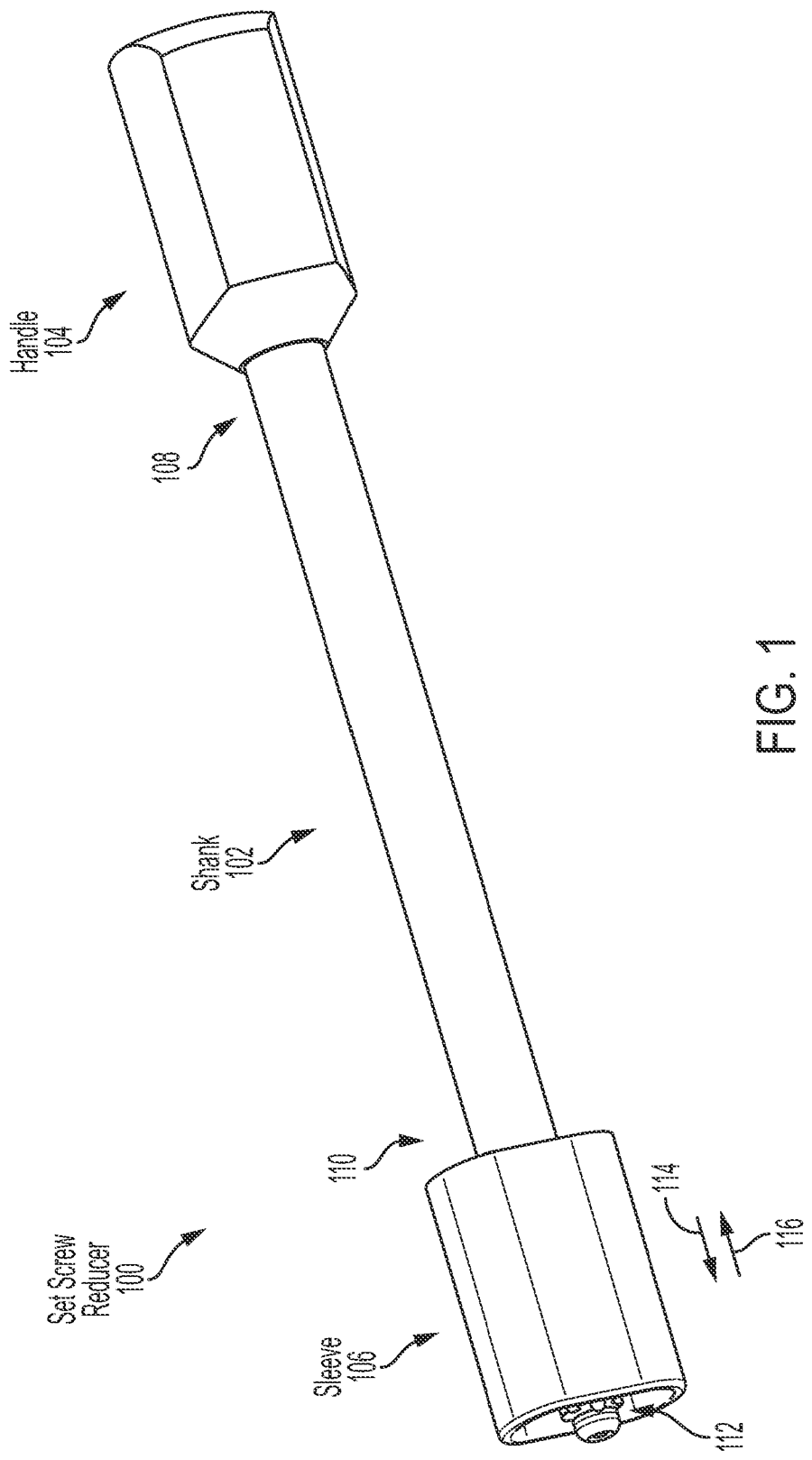
Spinal Frontiers is a trademark of NSpine GmbH.
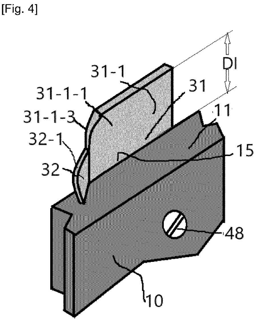
Information only, summarised from third-party sources: not medical, legal, regulatory or financial advice. Full disclaimer.

© 2013 – 2026 NSpine Limited. Privacy notice.